
Manual

Spectrex Inc. - SharpEye
TM
UV/IR (F) Flame Detector Manual – TM756100 Rev A, July 2005
10
4. Operation
4.1 Visual Indications
One Red LED is located in the detector’s front window. In Alarm condition, the
LED is continuously ‘on’.
4.2 Output Signals
The detector includes the following control outputs:
• Alarm Relay
•
Fault Relay
• Voltage Level Output
5. Technical Specifications
5.1 Electrical Specifications
a. Operating Voltage: 18-32 VDC
b. Power Consumption:
Max. 70mA - Stand-by
Max. 130mA - Alarm
c. Electric input protection:
The input circuit is protected against voltage reversed polarity voltage transients,
surges and spikes according to MIL-STD-1275A.
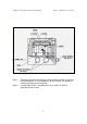
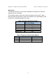
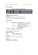
d. Electrical Interface
:
Terminals Function
1 POWER SUPPLY IN (+)
2 RTN
3 OUTPUT SIGNAL
4 ALARM RELAY (NO)
5 ALARM RELAY (C)
6 FAULT RELAY (NO)
7 FAULT RELAY (C)
The FAULT relay will be normally energized closed normal operation of the
detector. The contact will be open at FAULT condition or low voltage.