Ultra Fast UV/IR Flame Detector Model 20/20F User and Maintenance Manual TM756100 Rev A, July 2005 ATEX Approved Ex II 2G EExd IIB + H2 T5 EExde IIB + H2 T5 218 Little Falls Rd., Cedar Grove, NJ 07009 USA; Phone: +1 (973) 239 8398 Fax: +1 (973) 239 7614 Web-Site: www.spectrex.net; Email: spectrex@spectrex.
The SharpEye Optical Flame Detector described in this document is the property of Spectrex, Inc. No part of the hardware, software or documentation may be reproduced, transmitted, transcribed, stored in a retrieval system, or translated into any language or computer language, in any form or by any means, without prior written permission of Spectrex, Inc. While great efforts have been made to assure the accuracy and clarity of this document, Spectrex, Inc.
Spectrex Inc. - SharpEyeTM UV/IR (F) Flame Detector Manual – TM756100 Rev A, July 2005 TABLE OF CONTENT 1. Scope................................................................................................................1 1.1 Product Overview ........................................................................................1 1.2 Document Overview ....................................................................................1 2. Technical Description.........................................
Spectrex Inc. - SharpEyeTM UV/IR (F) Flame Detector Manual – TM756100 Rev A, July 2005 8.5 Maintenance Records ...............................................................................25 8.6 Troubleshooting.........................................................................................25 8.6.1 Fault Indication ...................................................................................25 8.6.2 False Alarm or Warning Indication ......................................................
Spectrex Inc. - SharpEyeTM UV/IR (F) Flame Detector Manual – TM756100 Rev A, July 2005 1. Scope 1.1 Product Overview The Flame detector Model 20/20F, with its ultra fast response, is designed to meet the two most important requirements for survivability: Fast Response Time (less than 5 milliseconds) and high reliability (immune to false alarms). The 20/20-F is sensitive to radiation in two frequency ranges of the electromagnetic spectrum: the infrared and the ultraviolet.
Spectrex Inc. - SharpEyeTM UV/IR (F) Flame Detector Manual – TM756100 Rev A, July 2005 2. Technical Description • Detection Range: Up to 20 ft (6m) for a 1ft x 1ft (0.3m x 0.3m) Gasoline fire. • • Ultra High Immunity to False Alarm (see section. 3.3.).
Spectrex Inc. - SharpEyeTM UV/IR (F) Flame Detector Manual – TM756100 Rev A, July 2005 2.3 Detection Levels Simultaneous detection of radiation in both the UV and the IR channels having an intensity, which exceeds detector’s preset Alarm level, will result in an Alarm signal.
Spectrex Inc. - SharpEyeTM UV/IR (F) Flame Detector Manual – TM756100 Rev A, July 2005 Figure 1.
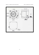
Spectrex Inc. - SharpEyeTM UV/IR (F) Flame Detector Manual – TM756100 Rev A, July 2005 Figure 2. Flame Detector Assembly - Schematic Section Note 1: Note 2: This figure describes the Detector, which includes Ground Terminal for ATEX installation. For FM installation, device includes 1/4” thread for external grounding screw mounting.
Spectrex Inc. - SharpEyeTM UV/IR (F) Flame Detector Manual – TM756100 Rev A, July 2005 3. Performance 3.1 Detection Sensitivity Detection sensitivity is the maximum distance at which the detector will reliably detect a specific size of fire & typical type of fuel (standard fire). Standard Fire: Standard fire is defined as a 1ft x 1ft (0.3m x 0.3m) Gasoline pan fire with max. wind speed of 6.5ft/sec (2m/sec). Detection Range: 20 ft (6 m) from 1ft x 1ft (0.3m x 0.3m) standard gasoline pan fire.
Spectrex Inc. - SharpEyeTM UV/IR (F) Flame Detector Manual – TM756100 Rev A, July 2005 Other Fuels: The Detector will react to other fuels in standard fire conditions at maximum response time of 3 seconds. The sensitivity range to other fuels varies according to the fuel type. Table 1 below provides the sensitivity to other fuels relative to (as a percentage of) the sensitivity to a standard gasoline fire source. Table 1. Response Sensitivity Ranges Type of Fuel % of Max.
Spectrex Inc. - SharpEyeTM UV/IR (F) Flame Detector Manual – TM756100 Rev A, July 2005 3.2 Cone Of Vision Horizontal: 90° Vertical: 70° Figure 3 illustrates the relative range as a function of the incidence angle. Figure 3.
Spectrex Inc. - SharpEyeTM UV/IR (F) Flame Detector Manual – TM756100 Rev A, July 2005 3.3 False Alarms The detector does not provide an alarm or a warning signal as a reaction to the radiation sources specified at Table 3 below. Notes: IAD = Immune at any distance. All sources are chopped from 0 to 20 Hz. * Will be the same immunity distance as indicated when not chopped. Table 3.
Spectrex Inc. - SharpEyeTM UV/IR (F) Flame Detector Manual – TM756100 Rev A, July 2005 4. Operation 4.1 Visual Indications One Red LED is located in the detector’s front window. In Alarm condition, the LED is continuously ‘on’. 4.2 Output Signals The detector includes the following control outputs: • Alarm Relay • Fault Relay • Voltage Level Output 5. Technical Specifications 5.1 Electrical Specifications a. Operating Voltage: 18-32 VDC b. Power Consumption: Max. 70mA - Stand-by Max. 130mA - Alarm c.
Spectrex Inc. - SharpEyeTM UV/IR (F) Flame Detector Manual – TM756100 Rev A, July 2005 e. Electrical Outputs: Relay Name Alarm Fault Table 4. Dry Contacts Relays Ratings Type Normal position Maximum Ratings SPDT SPST N.O. N.C. 5A at 30VDC or 250 VAC 5A at 30VDC or 250 VAC 5.2 Mechanical Specifications a. Enclosure: Aluminum: Chromate coating with Epoxy enamel finish or Stainless Steel 316: Electrochemical passivation coating b. Explosion Proof ATEX Ex II 2G SIRA 00ATEX 1160, 1162 T5 Temp.
Spectrex Inc. - SharpEyeTM UV/IR (F) Flame Detector Manual – TM756100 Rev A, July 2005 5.3 Environmental Specifications a. High Temperature: Design to MIL-STD-810C, method 501.1 procedure II Operating temperature: +70 °C (+160 °F) Storage temperature: +85 °C (+185 °F) b. Low Temperature: Design to MIL-STD-810C, method 502.1, procedure I Operating temperature: -40 °C (-40 °F) Storage temperature: -55 °C (-65 °F) c. Humidity: Designed to meet MIL-STD-810C, method 507.
Spectrex Inc. - SharpEyeTM UV/IR (F) Flame Detector Manual – TM756100 Rev A, July 2005 6. Installation Instructions 6.1 Introduction This chapter does not attempt to cover all of the standard practices and codes of installation. Rather, it emphasizes specific points of consideration and provides some general rules for qualified personnel. Special safety precautions are stressed wherever applicable. 6.
Spectrex Inc. - SharpEyeTM UV/IR (F) Flame Detector Manual – TM756100 Rev A, July 2005 6.3 Preparations For Installation Installation should comply with regulations (e.g. NFPA 72E), as applicable to flame detectors. The detectors can be installed with the use of general-purpose common tools and equipment. 1 Verify the appropriate Purchase Order. Record the part number and Serial number of the detectors and the installation date in the appropriate Logbook.
Spectrex Inc. - SharpEyeTM UV/IR (F) Flame Detector Manual – TM756100 Rev A, July 2005 6.5 Detector Mounting The detector may be mounted on a simple fabricated bracket, or preferably the optional Spectrex Swivel Mount, Model No. 20/20-003. The Swivel Mount enables the detector to be rotated up to 40 degrees in all directions. 6.5.
Spectrex Inc. - SharpEyeTM UV/IR (F) Flame Detector Manual – TM756100 Rev A, July 2005 Description 1 Protective Set Screws 2 Ground Terminal (for ATEX) or Ground Thread (for FM) 3 Back Cover 4 Housing 5 Detector Mounting Screws 6 Swivel Mount Figure 4.a.
Spectrex Inc. - SharpEyeTM UV/IR (F) Flame Detector Manual – TM756100 Rev A, July 2005 Description 1 Swivel Mount Screw Hole 2 Swivel Mount 3 Holding Plate 4 Locking Screws 5 Detector Mounting Screws 6 Swivel Mount Plate Figure 4.b.
Spectrex Inc. - SharpEyeTM UV/IR (F) Flame Detector Manual – TM756100 Rev A, July 2005 6.6 Wiring (Refer to Fig. 5) 1 2 Disconnect power. Remove the four protective set-screws (Fig 4a, item 1) from detector front. 3 Release the four socket-head screws that secure the detector housing (Item 1) to its back cover (Item 4) using No. 5 Hex Key for M6 screw. Hold the housing during the removal of the screws. With the screws removed, pull the detector housing from its cover.
Spectrex Inc. - SharpEyeTM UV/IR (F) Flame Detector Manual – TM756100 Rev A, July 2005 6.7 Terminal Wiring (Figure 6) The detector contains a terminal board labeled 1 to 7. The following describes the function of each electrical terminal of the detectors. Power Supply: (Terminals 1, 2) Input power is supplied to terminal No. 1. The RETURN is connected to terminal No.2. Manual Bit Activation: (Terminal 3) Terminal No. 3 is used for the manual BIT activation.
Spectrex Inc. - SharpEyeTM UV/IR (F) Flame Detector Manual – TM756100 Rev A, July 2005 1 2 3 4 5 6 Figure 5.
Spectrex Inc. - SharpEyeTM UV/IR (F) Flame Detector Manual – TM756100 Rev A, July 2005 Figure 6.
Spectrex Inc. - SharpEyeTM UV/IR (F) Flame Detector Manual – TM756100 Rev A, July 2005 7. Operating Instructions 7.1 Scope The following instructions are designed to obtain optimal performance from the detector over its life-cycle. 7.2 Power-Up 1 2 3 4 Apply power and wait up to 10 seconds; verify that the FAULT Relay closed contact (short between Terminal 6 and 7) Wiring inspection. If a short-circuit or line discontinuity exists, indications will appear on the control unit display panel.
Spectrex Inc. - SharpEyeTM UV/IR (F) Flame Detector Manual – TM756100 Rev A, July 2005 7.4 Safety Precautions After powering-up, the detector requires minimal attention in order to function properly, but the following should be noted 1 Follow the instructions in the manual and refer to the drawings and specifications issued by the manufacturer. 2 Do not expose the detector to radiation of any kind unless required for testing purposes. 3 Do not open the detector housing, while power is supplied.
Spectrex Inc. - SharpEyeTM UV/IR (F) Flame Detector Manual – TM756100 Rev A, July 2005 8. Maintenance Instructions 8.1 Scope This chapter deals with preventive maintenance, describes possible faults in detector operation and indicates corrective measures. Ignoring these instructions may cause problems with the detector and any invalidate the warranty. Whenever a unit requires service, please contact the manufacturer or its authorized distributor for assistance. 8.
Spectrex Inc. - SharpEyeTM UV/IR (F) Flame Detector Manual – TM756100 Rev A, July 2005 8.5 Maintenance Records It is recommended to record maintenance operations performed on a detector in a System Log Book. The record should include information, which identifies the unit, installation date, contractor, and entries for every maintenance operation performed including the description of the operation, date and personnel ID.
Spectrex Inc.
Spectrex Inc. - SharpEyeTM UV/IR (F) Flame Detector Manual – TM756100 Rev A, July 2005 Appendix A - Wire Selection Tables GENERAL INSTRUCTION FOR ELECTRICAL WIRING: 1. Refer to Table 7 to determine the required wire gauge for general wiring, such as relay wiring. Calculate the permitted voltage fall with respect to loads current, wire gauge, length of wires. 2. Refer to Table 8 to select wire gauge for detectors power supply wires. DO NOT connect any device or load to detectors supply inputs. Table 7.
Spectrex Inc.
Spectrex Inc. - SharpEyeTM UV/IR (F) Flame Detector Manual – TM756100 Rev A, July 2005 Appendix B. Typical Wiring Configurations Wiring for Four Wire Controllers: Figure 7.
Spectrex Inc.
Spectrex Inc. - SharpEyeTM UV/IR (F) Flame Detector Manual – TM756100 Rev A, July 2005 Appendix C. Mounting the “EExde approved” version The EExde approved version provides an additional EExe terminal box attached below the EExd detector and therefore allows easier access in hazardous areas (see fig. 10). The unit is prewired to the terminals in the additional EExe terminal section ready for field wiring connections 1.
Spectrex Inc. - SharpEyeTM UV/IR (F) Flame Detector Manual – TM756100 Rev A, July 2005 2. Wiring Refer to Fig. 8. 1 Disconnect power. 2 Release the four (4) slotted-head screws (Item 3) that secure the chamber cover (Item 2). The chamber is now revealed. 3 Remove the protective plug mounted on the detector conduit inlet, pull the wires through the detector chamber (Item 7). Use M25x1.5 explosion-proof cable entry to assemble the cable to the detector.
Spectrex Inc. - SharpEyeTM UV/IR (F) Flame Detector 1 2 3 4 Manual – TM756100 Rev A, July 2005 Description Modified Back Cover 5 Ground Terminal Chamber Cover 6 Mounting Thread Slotted Screw 7 Chamber Terminal Block 8 Cable Inlet (M25 x 1.
Spectrex Inc. - SharpEyeTM UV/IR (F) Flame Detector Manual – TM756100 Rev A, July 2005 2.1 Terminal Wiring The detector contains a chamber consisting of a terminal block (Item 4). The terminal block is labeled 1 to 6. (See Fig. No.9.) Power Supply (Terminal Numbers 1, 2):Input power is supplied to Terminal No. 1.RETURN is connected to Terminal No. 2. Alarm Relay (Terminal Numbers 3, 4): The Alarm output is a NO. SPST contact at Terminal Numbers 3 and 4. The contacts are closed at Alarm Mode.
Spectrex Inc. - SharpEyeTM UV/IR (F) Flame Detector Manual – TM756100 Rev A, July 2005 Appendix D. Long Range UV/IR Fire Simulator Figure 10: Fire Simulator Product Description The SharpEye UV/IR Long-Range Fire simulator 20/20-311 is designed specifically for use with the UV/IR or UV flame detectors. The Fire Simulator emits UV/IR radiation in a unique sequential pattern corresponding and recognizable by the detector as fire.
Spectrex Inc. - SharpEyeTM UV/IR (F) Flame Detector Manual – TM756100 Rev A, July 2005 Figure 11: UV/IR Detector Target Point Caution: 1 The following test will simulate a real fire condition and may activate the extinguishing system or other alarms. If this is not desired, disconnect them before the test and reconnect after the simulation. Follow these instructions to simulate a fire: 1 Aim the Fire Simulator towards the detector’s “Target Point” (see Fig.
Spectrex Inc. - SharpEyeTM UV/IR (F) Flame Detector Manual – TM756100 Rev A, July 2005 Battery Charging 1 The Fire Simulator uses NiCad batteries as a rechargeable power source. When the batteries are fully charged it will operate for at least 60 uses without recharging. An internal buzzer is sounded when the voltage from the batteries is lower than the required operational level. 2 Place the Fire Simulator into the storage case on a table in a safe area.
Spectrex Inc. - SharpEyeTM UV/IR (F) Flame Detector Manual – TM756100 Rev A, July 2005 Specifications Mechanical Explosion Proof Enclosure: FM (designed to meet) Class I, Division 1 & 2 Groups B, C and D Class II, Division 1 & 2 Groups E, F, and G ATEX EX II2G NEMKO 02ATEX255 EExd IIB T5 50˚C per En 50-014 & EN50-018 Electrical Power: 8 VDC Max 6 x Rechargeable1.2 VDC NiCd Batteries Current: 2.5A Avg.
Spectrex Inc. - SharpEyeTM UV/IR (F) Flame Detector Manual – TM756100 Rev A, July 2005 Technical Support For all technical assistance or support, contact: 218 Little Falls Road Cedar Grove, NJ 07009, USA Tel: +1 (973) 239 8398 Fax: +1 (973) 239 7614 Email: spectrex@spectrex.net Web-site: www.spectrex.net Your Local Office: SPECTREX INC. Texas (USA) Mr. Jay Cooley, Regional Sales Manager 16203 Park Row, Suite 150 Houston, Texas 77084 USA Phone: +1 (832) 321 5229 Email: jay@spectrex.net Europe Mr.