Survey Pro Field Software User Guide From V5.
SOFTWARE END USER LICENSE AGREEMENT IMPORTANT, READ THIS AGREEMENT CAREFULLY. BY INSTALLING OR USING ALL OR ANY PORTION OF THE SOFTWARE, YOU ARE ACCEPTING ALL OF THE TERMS AND CONDITIONS OF THIS AGREEMENT. YOU AGREE THAT THIS AGREEMENT IS ENFORCEABLE LIKE ANY WRITTEN AGREEMENT. IF YOU DO NOT AGREE TO ALL OF THESE TERMS AND CONDITIONS, DO NOT USE OR ACCESS THE SOFTWARE.
Software and that irrespective of any use of the words “purchase”, “sale” or like terms hereunder no ownership rights are being conveyed to you under this Agreement or otherwise. 4.Payment You shall pay all fees associated with the Software licensed and any services purchased hereunder as set forth in the applicable Order Form. All payments shall be made in U.S. dollars within thirty (30) days of your receipt of the applicable invoice, unless otherwise specified in writing by the Licensor Supplier.
United States or foreign agency or authority. You agree to the foregoing and warrant that you are not located in, under the control of, or a national or resident of any such prohibited country or on any such prohibited party list. The Software is further restricted from being used for the design or development of nuclear, chemical, or biological weapons or missile technology, or for terrorist activity, without the prior permission of the United States government. 12.General. 12.1.Assignment.
Table of Contents 1. Welcome to Survey Pro ..............................................................................................1 Scope......................................................................................................................1 Conventions Used .....................................................................................................2 2. Introduction to the Survey Pro User Interface ...............................................................
Introduction to Calibration ................................................................................... 44 Calibration Procedure, Illustrated ......................................................................... 45 Special Case of One-Point Calibration ................................................................... 48 How Survey Pro Deals With Base Location............................................................. 48 Unexpected Change of Base ..............................................
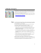
1. Welcome to Survey Pro Congratulations on your decision to purchase a Spectra Precision product. Spectra Precision is serious about providing the best possible products to its customers and knows that you are serious about your tools. We are proud to welcome you to the Spectra Precision family. The Spectra Precision Survey Pro team is continually improving and updating Survey Pro. Please take a few minutes to register by visiting our web site at: http://www.spectraprecision.com/register.
Conventions Used The following conventions are used: • Text strings in bold font represent the names of software items such as fields, buttons, check boxes, tabs, messages, screens, menus, etc. • The symbol “>” is placed between menus, tabs and/or buttons to indicate that you have to tap on these parts successively in that order. • When referring to both optical instruments and GNSS receivers, the term “instruments” will be used to encompass the two types of equipment.
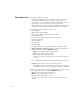
2. Introduction to the Survey Pro User Interface Home Screen and Main Menu On launching Survey Pro, you will first be asked to open a job. When done, the software will open at the Home screen. The home screen shows a selection of the functions you will most frequently use in the field. You can customize the Home screen based on your needs.
Switching Between Home Screen and Main Menu The table below lists the buttons allowing you to navigate between the Home screen and the Main Menu and its submenus. Icon / Check boxes Result Takes you to the Home screen from the Main Menu or any submenu. Takes you back to the Main Menu from the Home screen. Takes you back to the Main Menu from an open submenu. The default Home screen has only one page so there’s only one blue dot (a radio button), and it is necessarily checked.
• Battery Level [3]: The battery icon displays the condition of the data collector’s rechargeable battery. The icon has five variations depending on the level of charge remaining, and a sixth variation to indicate battery charging. Icon Meaning 100% charge remaining 75% charge remaining 50% charge remaining 25% charge remaining Less than 5% charge remaining Battery charging from AC adaptor Tapping the battery icon is a shortcut to the Windows Mobile Power Settings screen.
Adding a Function This is a three-step procedure: • Go to the Main Menu, then to the submenu containing the function you would like to add to the Home screen. • Tap and hold the corresponding function item and select Add to Home. Survey Pro then shows the Home screen with all the possible free locations for the new function, all represented as unnamed icons. Note at this point that all the icons are shown with the same background color (see example).
Screen Details The screen example below illustrates the different types of items you will usually encounter on the screen when using the different Survey Pro functions: [1] [4] [3] [5] [6] [2] [7] • Input Field [1]: An area where you can enter a specific value. • Output Field: Only displays a value that cannot be changed. • Simple Button [2]: Typically used to run the function described by its name. Just tap it to run the function.
The following buttons will appear in the area usually occupied by the command bar. Item Function OK button. Accepts the changes made and closes the window. Cancels the changes made in the open window Closes the current window Quick access to the relevant Settings screen Quick access to the Help system Quick access to the Quick Pick list. Map View The map view is a graphical representation of the objects in the current job. It will show basemaps in the background if you are using one (see screen example).
The main map can also function as an interface to collect measurements. Tap and hold on the main map and choose Survey Mode to enable the Measurement interface (see screen example for GNSS). When in Survey Mode, you can collect data from the main map by tapping on one of the available buttons (see table below). You can also press the Enter key to trigger an observation. By default, the Enter key will trigger a “Topo” observation.
3. Creating a Job Survey Pro cannot start without a job being open. Upon launching Survey Pro, the Welcome to Survey Pro screen will guide you through the process of creating a new job or opening an existing job. NOTE: Upon launching the onboard version of Survey Pro, the initial screen allows you take measurements without having to open a job. Refer to 8. Survey Pro’s On-Board Version on page 58. • Tap the New button.
Job Settings The settings and values entered for a new job become the default values for any subsequent new jobs. A short description of the jobs settings is given below. [1] [2] • Units [1]: When creating a new job, set all the desired units for the job. You can also enable the setting for Earth Curvature and Refraction correction for optical measurements. • Control File [2]: Control points can optionally be imported from another existing job by checking the Use a Control File check box.
– Clear the check box when you are doing an optical survey with a ground scale factor of 1, or if you are doing a GNSS survey and there’s no known projection or datum for your local grid coordinates. – Check this box when your local grid coordinates are defined by some known map projection and datum. Understanding Scale Factor for your coordinate system: – If your job has “no coordinate system”, Survey Pro automatically sets the scale factor for optical measurements to “1.0”.
Survey Pro will parse and import all the known elements from the chosen file. These elements will be added to the current job as points, polylines and alignments. See the definition of these elements in Editing Points on page 13, Editing Polylines on page 14 and Editing Alignments on page 14. The File > Import Control function is used to import points onto the control layer of your job. Points on the control layer are protected from being modified. Control files should be in *.Survey or *.JOB format.
When there is no projection set or solved, there is no way to transform the keyed in values into grid or geodetic coordinates. You will see these coordinates are missing when you look at the point details. If this point is derived from an observation, the Location tab will list its current coordinates but these cannot be edited. For more information on Descriptions, Layers and Features, see Appendix on page 64. 14 Editing Polylines A polyline in Survey Pro is a line connecting points together.
4. Connecting Survey Pro to an Instrument Before you start taking new measurements in a job, you must tell Survey Pro if an optical instrument or a GNSS receiver will be used to perform the job. NOTE: Selecting an instrument only makes sense when Survey Pro is running on a data collector. If it’s running in the instrument you are using (e.g. FOCUS 30), only this instrument can be used in Survey Pro. Before you make this choice, power on the instrument.
In • • • • Connecting Survey Pro to an Optical Instrument summary, tapping the Instrument icon allows you to: Select Optical, GNSS or Post Processing mode Quickly activate an instrument for use in the selected operating mode Quickly access the Instrument Settings screen Add a new instrument supported in the selected operating mode. • Tap the Instrument icon and select Switch to Optical • Tap the Instrument icon and select Manage Instruments.
Remote Control Screen If you are using a robotic total station, use the Survey > Remote Control function to control the total station from the data collector running Survey Pro.
Connecting Survey Pro to a GNSS Receiver • Tap the Instrument icon and select Switch to GNSS (or Switch to Post Processing) • Tap the Instrument icon and select Manage Instruments. This opens the Settings screen listing the current GNSS receiver profiles. • Tap Add Receiver. • Use one the following two buttons to establish a connection with the receiver: 1. Start Spectra Precision Scan: Tap this button to let Survey Pro search automatically for new Spectra Precision GNSS receivers over Bluetooth.
Then tap Connect. The receiver will provide its model, serial number and capabilities (the GNSS receiver can potentially be used as a rover, a base, or for data collection). The icons used to describe these capabilities are listed below. Icon Capability Rover capability Base capability Data collection capability (for post processing) You can also change the receiver name if you wish (default name: model name + last four characters from serial number). Then tap Save.
Additional Settings Once connected to a GNSS receiver, additional settings are needed to complete its configuration. These are accessible through the icons next to each receiver profile. From left to right: Icon or or Function Shown when respectively a Bluetooth or cable connection has been set between Survey Pro and the receiver (see connection procedure above). If the Bluetooth icon is shown, tapping this icon will provide the receiver brand and model as well as the receiver Bluetooth name.
Checking the GNSS Status Checking the GNSS status is an important step before starting a job.This implies that the receiver is in real conditions of use, preferably in an open sky environment. Use the GNSS Status function on the Survey menu to read this information.
5. Optical Surveying What you have done already: • You have set up the optical instrument on a tripod over a point of your choice and measured the instrument height. • You have selected Optical from the instrument icon located on the Home screen or Main Menu. • You have activated the instrument for use with Survey Pro. See Connecting Survey Pro to an Optical Instrument on page 16. • You have configured the proper settings in the Job > Settings > Surveying tab.
Instrument Setup Station Setup on a Known Point The name and coordinates of the known point where the station is set up can be picked from within the open job. This method offers three different scenarios: • BS Azimuth [1]: Backsight azimuth. The station location will be set from the coordinates of the known point. The circle is set using the value you enter in the Backsight Circle field. The backsight azimuth will be the value you enter.
Start the station setup as follows: • Go to the Main Menu, then tap Survey > Station Setup. • Choose Setup Type= Known Point. • Enter the name of the station setup point in the Occupy Point field. The point name can be entered directly, or, picked from the map or point list using the button. • If you wish to ignore elevations in your job, check the 2D Survey box. You will otherwise enter the HI (height of instrument) field. • Tap Next.
2. If you choose BS Point: • Enter the name of the backsight point. It can also be picked from the map or the list of points. • Specify the type of target used at the backsight point (Fixed Target or Roving Target). A “roving target” is when you measure to the backsight with the same rod and prism you will be using for your subsequent data collection.
you choose New Point: Place a target at the unknown (new) backsight point. Aim the instrument at this point. Enter the known or an assumed value of azimuth along this direction. Enter the desired value of backsight circle for this direction (typically “0” or true azimuth). If the Survey with True Azimuths setting is enabled, then the circle value will automatically be set by Survey Pro. – Tap Set Circle. – Specify the type of target used at the backsight point (Fixed Target or Roving Target). 3.
• Go to the Main Menu, then tap Survey > Station Setup. • Choose Setup Type= Unknown Point/Resection. • Use the Store Pt and Description fields to enter respectively the name and description of the point where the instrument is set up. (This is a new point, with unknown coordinates.) • If you will ignore elevations in your job, check the 2D Survey box. You will otherwise enter the height of instrument in the HI field. • You can take one or more shots of each point.
Alternatively, you can tap Backsight to proceed to the normal backsight setup, with your newly calculated station point as the setup point, and your first resection point as the backsight point. It is a good practice to do a backsight check after a resection to ensure the instrument circle is oriented as you expected. When this is done, tap Finish. You can now start measuring new points.
Remote Elevation This routine will set the elevation coordinate of the station from a point with known elevation. It is accessible from within the first station setup screen by tapping the Remote Elevation button (provided the 2D Survey box is unchecked). The point with known elevation is either: • A point stored in the job. You will select it from the map or the list of points.
Sideshot • Be sure the instrument is pointed at the target placed over the point. • Tap Sideshot. Survey Pro returns the results of the measurement in the lower portion of the screen ([1]). The point name is automatically incremented for the next measurement. Tapping on the Result tab will provide more information on the measurement made ([2]). [1] [2] Point: Point name N: Point coordinate Y E: Point coordinate X Elev.
Traverse • Be sure the instrument is pointed at the target placed over the point. • Tap Traverse. The screen prompts you to measure a new point, or to pick a point that was previously measured from the current station setup (Survey Pro will display a list of appropriate points), and then move the instrument to that point. If you create a new point to traverse to, you will then be asked to enter the description of the point before measuring it.
Repetition Shots The Repetition shots function allows you to perform sideshots or traverse shots using any number (between 1 and 99) of repeated measurements (“Sets”). • Go to the Survey menu and tap Repetition Shots. • Tap in the command bar to access the job settings relating to repetition shots (equivalent to navigating to the Job > Settings > Repetition tab). • Tap the Repetition tab.
EXAMPLE: If you had three complete sets, then selected to toss the worst HA, you would now have two HA sets, three ZA sets and three SD sets. If you tapped HA, you would collect an additional set of horizontal angles only, and on return to this screen, you would now have three HA, three ZA, and three SD sets. If you hit HA again, on return to this screen you would have four HA, three ZA and three SD sets.
6. GNSS Surveying Starting an RTK Base NOTE: You don’t need to set up a base if you are working in a network. Just make sure your rover is configured to receive network corrections, and actually receives them before you start taking measurements in your job. See Starting an RTK Rover on page 36. What you have done already: • You have made sure your GNSS receiver is fitted with the device (Internet or radio modem) required to operate the data link over which base corrections will be sent to the rover.
• Tap Connect. When creating a job, if you decided not to choose a coordinate system, you will be asked to reconsider this choice when starting the base. The Start Survey Prompt Projection screen will appear at this time with two possible options: 1. Ground Calibration: Choose this option if there is no known projection or datum to relate your local grid coordinates to geodetic coordinates (through this choice, you confirm your decision to use local control to set up a coordinate system).
Starting an RTK Rover This section describes how to configure and start an RTK rover. What you have done already: • You have made sure your GNSS receiver is fitted with the device (Internet or radio modem) required to operate the data link providing the rover with base corrections. • You have set up the GNSS receiver on a pole and measured the antenna height. • You have selected GNSS from the instrument icon located on the Home screen or Main Menu.
This is all you need to set if your network is an Internet server for GNSS corrections, either an NTRIP mount point, or a direct IP connection. If the network connection is to a static IP base modem, you must also specify the server type as Static IP Base, and select a correction format. If you set up your own base just before, Survey Pro will automatically choose the same correction format at the rover.
• While the rover receives data (corrections and position) from the base, enter the antenna height you measured previously (Measured field) and how you measured it (To field). You may ask the rover to log raw data (for post-processing) by just specifying a recording interval in the Post Processing Recording Interval field. If you earlier set up a base doing the same, then make sure you are using the same recording interval for both receivers. Select “Off” if data logging is not required. • Tap Next.
Some routines, such as point stakeout or offset points, cannot be run until the calibration is properly solved. • Before starting data collection, tap in the command bar. This directly opens the Meas. Mode tab (part of the Job Settings screen) where you can set the acceptance criteria for different types of point collection: – On the Data tab, define the criteria for all the points you will collect using Point from the Data Collection screen or from the active survey map.
• Tap Collecting Data to save your settings. Survey Pro displays the Data Collection screen. Standard data collection routines are presented below. Keep in mind that you may have to solve the calibration before your measured GNSS coordinates are properly transformed into your local grid (see Solving Calibration on page 44). Remember also that you can access the data collection functions from the active map after you have tapped and held on the map and selected Survey Mode from the popup menu.
NOTE: You can tap the Wait xx button to accept the point before the minimum duration has expired. You will in return be informed that the minimum duration is not yet met, at which point you can discard the warning by tapping Accept anyway. • Average for cleared: Screen type [2] will be displayed for an unlimited period of time, until you tap Accept. Point collection is then complete, unless some other acceptance criteria are not met in which case you will see screen type [3] after you tap Accept.
Collecting Features Tap Feature on the Data Collection screen. Features can be collected using one of the methods below. In all methods but the last one, each new point name is incremented automatically to the next available name. • Time Interval: After accepting the first point, additional points will automatically be stored after the specified time interval (in seconds) has elapsed.
Collecting Offset Points • Tap Offset on the Data Collection screen. • Enter the offset point name and description. • Tap Azimuth/Bearing to indicate that you will be measuring either the azimuth or bearing angle from the occupy point to the offset point.
Solving Calibration Introduction to Calibration A GNSS calibration is a 2D similarity transformation. The GNSS LLH coordinates are transformed using a map projection into XY mapping plane coordinates. The XY mapping plane coordinates are then translated, scaled and rotated into your local grid using the calibration. Your choice of projection mode will determine the mapping plane used for this procedure: 1.
Calibration Procedure, Illustrated The calibration procedure can be split into three distinct steps. These are described below as flowcharts: • Step 1: When you start a survey, Survey Pro will report the need for calibration on the Calibration Status page, which will guide you through the process of collecting the minimum amount of control points required for a unique solution of the calibration.
• Step 2: The Calibration check page will guide you through the process of collecting an additional GNSS control point to check the solution, and to provide redundancy for the best fit least squares solution.
• Step 3: The calibration results page will solve the calibration and display the results. From Step 2 Control points are spaced evenly and have good geometry? Yes Blunders Detected Blunder Detection Runs No Yes No No Blunders Detected Tap Finish to accept the solution anyway To Step 2 Tap Add Point to collect more control points, as in Step 2.
After you have solved the calibration as part of the Start Survey wizard, you can use the Survey > Control > Control routine, or the Survey > Projection > Solve Calibration > Add Point routine to add additional GNSS control points, re-solve the calibration, and have all the collected points updated with the latest calculation.
With a known coordinate system used: • If you set up the base on a known point, the selection of a known coordinate system will allow Survey Pro to compute and attach the equivalent geodetic (LLH) coordinates to that point. • If you set up the base on an unknown point: Same as with no coordinate system used. Unexpected Change of Base Typically when working in a VRS network, your rover may detect a change of base location in the corrections it receives. In that case Survey Pro will warn you of that change.
7. Stakeout Routines This section introduces the basic stakeout routines with optical and GNSS instruments. When you become familiar with these routines, you will be able to extend your knowledge on more specific stakeout routines, such as stake to line, slope staking, etc. What you should have done already: • You should have now completed the station setup with your optical instrument. • You should have now solved the calibration with your GNSS receiver.
The following appears when zeroing the circle: – A new backsight circle value is computed, sent to the instrument and stored in the raw data. – The Angle Right value is changed to zero to reflect the change (see example). The instrument now needs to be turned horizontally to zero to face the design point. – To prevent errors, the backsight setup is invalidated when exiting the Stakeout function.
Staking Points With a Robotic Optical Instrument • Go to the Stakeout menu and tap Stake Points. • Use the Design Point field to enter the name of the first point you want to stake. • Enter an integer in Increment. This will allow Survey Pro to automatically select the next design point to stake once the current one has been staked. e.g. “ST101” first staked and Increment= 2, then next point will be “ST103”.
When you get closer to the design point, the graphic will change to assist you in more precisely locating the design point. The point to stake becomes the fixed center of the display and the rod becomes the object that is moving. This aids in precisely positioning the rod over the point. A red arrow indicates the direction in which to go. 1. Distance to go is between 3.0 and 0.3 m (10 and 1 ft): Four dark-green spots appear around the graphic. 2. Distance to go is less than 0.
Staking Points With GNSS • Go to the Stakeout menu and tap Stake Points • Use the Design Point field to enter the name of the first point you want to stake. • Enter an integer in Increment. This will allow Survey Pro to automatically select the next design point to stake once the current one has been staked. e.g. “ST101” first staked and Increment= 2, then next point will be “ST103”. (Tapping the Next Point button will instantly select the next point from the list, based on the Increment value.
Remember the rover receiver is always in dynamic mode (>ROVING button displayed) as you navigate to the design point: Symbol Meaning Design point location. Your current location. Reference point or azimuth. Scale used on the graphic. Represents the circle radius. Go N/S: xxx Go E/W: xxx Horizontal and vertical components of the distance still to go. FILL/CUT: xxx NOTE: You can use the Topo SS button any time along the way to store any point of interest.
• When you have located the design point and you wish to collect a static RTK occupation at this point in order to get a more precise position averaged from multiple epochs, you should toggle to occupying mode by tapping the >ROVING button (which is then changed into an >OCCUPYING button). This will turn the receiver into static mode for the occupation. • When you are satisfied with the occupation results, you can tap Accept to finish the stakeout measurement.
• Stake to Line: Allows you to locate any position in relation to a predefined line. The line can be defined by two points, a point and direction, a polyline or the centerline of an alignment. Distance, direction and cut/fill information is provided so the rod/the rover can locate the line by traveling the shortest possible distance (a perpendicular offset to the line).
8. Survey Pro’s On-Board Version Survey Pro is used on board a Nikon Nivo or Spectra Precision FOCUS total station. After you have powered on the instrument, wait until the screen displays the desktop. Then do the following: • Double-tap the Survey Pro icon: . Survey Pro starts initializing the instrument. The Level Bubble screen is then shown (see screen example). • Level the instrument and enable or disable the compensator, as required. • Tap when done. This opens the Quick Shot screen.
Mechanical Instrument: [1] [3] [4] [5] [6] [7] [8] [9] [10] [13] [14] [15] [16] [17] Command bar: • [1]: Provides access to on-board help. • [2]: (Robotic instrument only) Denotes keyboard used in numeric mode. • [3]: Provides status of visible laser pointer: – : Off. Tapping this icon will toggle it On. NOTE: Standard safety precautions should be taken to ensure that persons do not look directly into the beam. – • • • • : On. Tapping this icon will toggle it Off.
• [8]: Provides access to Survey Pro settings: – Units tab: Used to set distance and angle units, directions, azimuth type and the order in which to display/deliver coordinates. – Format tab: Used to set the number of decimal places displayed by the instrument for each type of measurement. – Quick Shot tab: Used to choose which results to display (HA, ZA, SD or HA, HD, VD) and which function to assign to the Measurement key (Measure Only or Measure and Store). Measure and Store requires an open job.
Target management: (Item [15]) on the screen example.) • HR field: Enter the height of rod for the selected target • / button: Specify the type of target used. Also provides access to the management of smart targets. • Choose the EDM measurement mode.
Working With a Job Open If you open or create a job using button [13], the Quick Shot screen will then show different options. Robotic Instrument: [10] [11] [19] [12] [13] [20] Mechanical Instrument: [10] [13] [19] [20] The differences are listed below: • [10]: With a job open, the Quick Stake screen can be accessed through this button. The Stakeout, Station Setup and Check Setup functions can be accessed by clicking on the arrow to the left of this button. • [11] and [12]: Same as with no job open.
Shot tab if you plan to store measurement data (see [8] described earlier in this section). With a job open, you can perform a lot of the most commonly used functions from the Quick Shot screen. To access the full set of Survey Pro functions, you can close the Quick Shot screen and access the Survey Pro main menu. NOTE: To access the Quick Shot screen at any time, simply press the “star”/F1 hard key on the instrument.
Appendix Descriptions [1] [2] A description may be defined for each point you store in a job (e.g. tree, pavement). You can create a description list to automate the task of entering descriptions for points when they are stored. This is particularly useful when the same description is used frequently. A description list is stored in Survey Pro as a description file (a TXT file you store in /Survey Pro Jobs/ for example), which may be in two different formats.
Memo for GNSS Users • You are using the following equipment: – a Bluetooth-equipped Spectra Precision GNSS receiver capable of detecting automatically the format of received corrections. – A data collector fitted with Bluetooth and an embedded GSM modem. • You are working in a network (remote base) over the Internet. • You are using a known coordinate system (and possibly a geoid). • You want to start your project from a new, empty job file.
Index Numerics 2D Survey 24, 27, 29 3D position solution 21 A Accept Anyway 41 Acceptance criteria (GNSS) 39 Activate 16 Active map 8 Add Network 36 Add Receiver 18 Add to Home 6 Alignments 14 All 32 Allow in PPK Survey 39 Angle only 27 Angle Right 30 Angle right 51 Antenna type 38 ATOM 34 Attributes 64 Automatic (choice of correction format) 36 Automatically accept when criteria is met 41 Average for 39, 40 Average of 32 Azimuth 43 Azimuth (entering) 2 Azimuth/Distance 54 B Backsight 28, 29 Base (change)
Level bubble 16, 58 Lights 16, 59 Line and Offset 57 LLH 2 Local geodetic 13 LockNGo 60, 61 LockNgo 17 M Main menu 3 Manage Instruments 15, 18 Manual Prompt Every Point 42 Manual mode 15 Manual Prompt Once 42 Map projection 12 Map view 4, 8 Mapping plane 35, 37 Meas.
Turn To 17 Turn to 60 TXT 12, 14 U Units 11, 60 Unknown Point/Resection 22, 27 Update Rate 42 Use Last Setup 22 V VD 60 Vertical distance 30, 43 View From Instrument to Rod (nonremote) 51 View From Instrument to Rod (remote) 52 Visible laser pointer 17 Visible laser pointer status 59, 61 VRMS 39 W Wait xx 56 Wait..
Survey Pro User Guide SPECTRA PRECISION Survey Support: e-mail: support@spectraprecision.com US & Canada: 1-888-477-7516 Latin America: +1-720-587-4700 Europe, Middle East and Africa: +49-7112-2954-463 Australia: +61-7-3188-6001 New Zealand: +64-4-831-9410 Singapore: +65-3158-1421 China: 10-800-130-1559 Contact Information: SPECTRA PRECISION DIVISION 10355 Westmoor Drive, Suite #100 Westminster, CO 80021, USA www.spectraprecision.