
Reference Manual


Table Of Contents
- Table of Contents
- Welcome
- Main Menu
- File Menu
- Job Menu
- Job Menu – GPS
- Job Menu – Basic GPS
- Survey Menu
- Backsight Setup
- Traverse / Sideshot
- Repetition Shots
- Multiple Sideshots
- Radial Sideshots
- Distance Offset Shot
- Horizontal Angle Offset
- Vertical Angle Offset
- Auto Collect
- Corner & 2 Lines
- Corner & Angle
- Corner & Offset
- Corner & Plane
- Surface Scan
- Video Scan
- Shoot From Two Ends
- Record Mode
- Resection
- Remote Elevation
- Check Point
- Solar Observation
- Remote Control
- Survey Menu – GPS
- Survey Menu – Basic GPS
- Leveling Menu
- Stakeout Menu
- Stakeout Menu – GPS and Basic GPS
- Inverse Menu
- Cogo Menu
- Curve Menu
- Roads Menu
- Adjust Menu
- Miscelaneous Screens
- Appendix A
- Index
Stakeout Menu
R-311
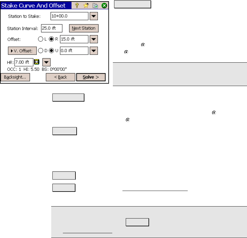
Next Station : advances the Station to Stake by
the Station Interval.
Offset: is the horizontal distance of the offset
from the specified curve. The offset occurs on
the left (while viewing the curve from the PC)
when the
L is selected or on the right when
the
R is selected.
Note: An offset of zero would result in the
specified curve being staked.
V. Offset : will result in the elevations for the design points to be
adjusted by the value entered here and will change the cut / fill
values accordingly. Design elevations will be lower when
D is
selected, and higher when
U is selected.
Grade : specifies a slope from the specified curve to the offset that
is being staked. When this is a non-zero value, the elevation for the
staked points will increasingly differ from the corresponding design
elevations on the specified curve as the Offset value increases.
Height of Rod: is the length of the rod.
< Back : returns to the previous screen.
Solve> : opens the third Stake Curve and Offset screen, described
next.
Note: A motorized total station will automatically turn toward the
design point after tapping Solve> , depending on the configuration of
the Stakeout Settings screen (Page R-50).