
Reference Manual


Table Of Contents
- Table of Contents
- Welcome
- Main Menu
- File Menu
- Job Menu
- Job Menu – GPS
- Job Menu – Basic GPS
- Survey Menu
- Backsight Setup
- Traverse / Sideshot
- Repetition Shots
- Multiple Sideshots
- Radial Sideshots
- Distance Offset Shot
- Horizontal Angle Offset
- Vertical Angle Offset
- Auto Collect
- Corner & 2 Lines
- Corner & Angle
- Corner & Offset
- Corner & Plane
- Surface Scan
- Video Scan
- Shoot From Two Ends
- Record Mode
- Resection
- Remote Elevation
- Check Point
- Solar Observation
- Remote Control
- Survey Menu – GPS
- Survey Menu – Basic GPS
- Leveling Menu
- Stakeout Menu
- Stakeout Menu – GPS and Basic GPS
- Inverse Menu
- Cogo Menu
- Curve Menu
- Roads Menu
- Adjust Menu
- Miscelaneous Screens
- Appendix A
- Index
Stakeout Menu
R-293
occurring below the selected node. Negative values result in the stake
location occurring above the selected node.
X-Slope (%): is the slope of the selected road section.
1/2 Road Width: displays the width of the selected road section
defined in the previous screen. This value can quickly be edited from
this field.
: opens the Smart Target options (Page R-456).
Backsight… : opens the Backsight Setup screen (Page R-122).
< Back : returns to the previous screen.
Solve > : opens the next screen.
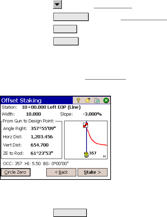
Offset Staking – Screen Four
The fourth Offset Staking screen displays the information needed to
aim the total station toward the selected design point.
Station: displays the current station and
section of the roadway being staked and the
current line segment type from the polyline
that describes the centerline. If staking the
center and an offset was specified, (To L) or (To
R) is also displayed to indicate if the offset is to
the left or right of the centerline, respectively.
Offset: displays the offset that is applied to the
design point.
Slope: displays the slope of the road at the
section being staked.
From Gun to Design Point: displays the angle and distance
information from the total station to the design point (plus offset if
specified).
Circle Zero : is used to modify the circle on the total station so that
the angle right reading will be zero when it is facing the current
target, which can sometimes be easier than turning to an obscure
angle value. When this button is tapped, the following actions will
occur: