
Reference Manual


Table Of Contents
- Table of Contents
- Welcome
- Main Menu
- File Menu
- Job Menu
- Job Menu – GPS
- Job Menu – Basic GPS
- Survey Menu
- Backsight Setup
- Traverse / Sideshot
- Repetition Shots
- Multiple Sideshots
- Radial Sideshots
- Distance Offset Shot
- Horizontal Angle Offset
- Vertical Angle Offset
- Auto Collect
- Corner & 2 Lines
- Corner & Angle
- Corner & Offset
- Corner & Plane
- Surface Scan
- Video Scan
- Shoot From Two Ends
- Record Mode
- Resection
- Remote Elevation
- Check Point
- Solar Observation
- Remote Control
- Survey Menu – GPS
- Survey Menu – Basic GPS
- Leveling Menu
- Stakeout Menu
- Stakeout Menu – GPS and Basic GPS
- Inverse Menu
- Cogo Menu
- Curve Menu
- Roads Menu
- Adjust Menu
- Miscelaneous Screens
- Appendix A
- Index
Stakeout Menu
R-279
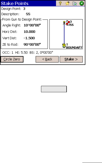
Stake Points – Screen Two
Design point: displays the name of the design
point that was entered in the first screen.
Description: displays the description assigned
to the design point.
Angle Right: is the horizontal angle to turn to
face the design point.
Horz. distance: is the horizontal distance from
the occupy point to the design point.
Vert Distance: is the vertical distance from the
occupy point to the design point.
ZE to Rod: is the zenith angle required to face the prism over the
design point.
Circle Zero : is used to modify the circle on the total station so that
the angle right reading will be zero when it is facing toward the
design point, which can sometimes be easier than turning to an
obscure angle value. When this button is tapped, the following
actions will occur:
1. A new backsight circle value is computed, sent to the
instrument and stored in the raw data
2. The Angle Right value is changed to zero to reflect the change.
The instrument now needs to be turned horizontally to zero to
face the design point.
3. To prevent errors, the backsight set up is invalidated when
exiting the Stakeout
dialog if this button has been used. A
circle zeroed on a design point is meaningless once the design
point has been staked.