
Reference Manual


Table Of Contents
- Table of Contents
- Welcome
- Main Menu
- File Menu
- Job Menu
- Job Menu – GPS
- Job Menu – Basic GPS
- Survey Menu
- Backsight Setup
- Traverse / Sideshot
- Repetition Shots
- Multiple Sideshots
- Radial Sideshots
- Distance Offset Shot
- Horizontal Angle Offset
- Vertical Angle Offset
- Auto Collect
- Corner & 2 Lines
- Corner & Angle
- Corner & Offset
- Corner & Plane
- Surface Scan
- Video Scan
- Shoot From Two Ends
- Record Mode
- Resection
- Remote Elevation
- Check Point
- Solar Observation
- Remote Control
- Survey Menu – GPS
- Survey Menu – Basic GPS
- Leveling Menu
- Stakeout Menu
- Stakeout Menu – GPS and Basic GPS
- Inverse Menu
- Cogo Menu
- Curve Menu
- Roads Menu
- Adjust Menu
- Miscelaneous Screens
- Appendix A
- Index
Survey Menu – GPS Module
R-209
Rover Setup
Survey Rover Setup.
The Rover Setup screen is used to set an RTK rover to begin receiving
differential corrections and to configure or check the base reference
position in Survey Pro. The Rover Setup screen is described as part
of the Start GPS Survey
wizard.
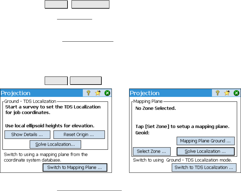
Projection
Survey Projection.
Ground TDS Localization Mode Mapping Plane Mode
The Projection Information
screen is used to select and solve the
horizontal and vertical projections, which are used to transform GPS
measured WGS84 coordinates (latitude, longitude, height) into local
coordinates (North,East,Elevation). The upper portion of the screen
displays the status and details on the current projection mode.
The screen is also used to switch between mapping plane and
localization mode. The buttons available will vary depending on the
current projection mode. TDS Localization mode is described in
detail starting on Page R-210 and Mapping Plane mode on Page R-
222.