SURVEY PRO For Pocket PC / Recon Reference Manual 2003 Tripod Data Systems, Inc.
TRIPOD DATA SYSTEMS SOFTWARE LICENSE AGREEMENT IMPORTANT: BY OPENING THE SEALED MEDIA PACKAGE, YOU ARE AGREEING TO BE BOUND BY THE TERMS AND CONDITIONS OF THE LICENSE AGREEMENT AND LIMITATIONS OF LIABILITY ("Agreement"). THIS AGREEMENT CONSTITUTES THE COMPLETE AGREEMENT BETWEEN YOU AND TRIPOD DATA SYSTEMS, INC. ("Licensor").
Table of Contents Reference Main Menu ........................................................................................ R-3 File Menu ........................................................................................... R-5 Open / New........................................................................... R-6 New Job .................................................................................. R-7 Save As .................................................................................
Auto Collect ......................................................................... R-91 Corner & 2 Lines ................................................................. R-94 Corner & Angle ................................................................... R-95 Corner & Offset ................................................................... R-96 Corner & Plane .................................................................... R-97 Shoot From Two Ends ..............................................
Corner Angle ..................................................................... R-173 Compute Area ................................................................... R-174 Triangle Solutions ............................................................. R-175 Map Check ......................................................................... R-176 Predetermined Area ......................................................... R-179 HD/VD to SD/ZA............................................................
Map Display Options ....................................................... R-245 Map View ........................................................................... R-246 Appendix A Transverse Mercator Zones .................................................A-1 Lambert Zones.......................................................................
Welcome Congratulations on your decision to purchase a Tripod Data Systems product. TDS is serious about providing the best possible products to our customers and know that you are serious about your tools. We are proud to welcome you to the TDS family. The TDS Survey Pro team is continually improving and updating Survey Pro. Please take a few minutes to register your copy so that you will be eligible for upgrades.
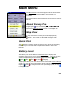
Main Menu The Main Menu is the starting point where all the other Survey Pro screens described in this manual are accessed. The small buttons at the bottom of the screen are used as follows: About Survey Pro Tapping the icon or selecting | opens the About Survey Pro screen. See Page R-26. Map View tapping the A map view of the current job can be displayed by button. This screen is described on Page R-246.
File Menu The File Menu contains routines to transfer files between the Survey Pro and another device.
Survey Pro Reference Manual Open / New The Open / New screen is used to open a recent job or create a new one. This screen also appears when Survey Pro is first started. : opens the job selected in the Open a Recent Job list. : will open the Open screen (Page R-10) where an existing job to open can be selected. : will open the New screen (Page R-7) where a new job can be created.
File Menu New Job The New Job screen is used to create a new project. Create a New Job Directory: displays the directory where the current job will be stored. Job Name: is where the name of the new job is entered. The default name is the current date. : allows you to select a different directory where to store the new job. : accesses the second screen where job details are defined.
Survey Pro Reference Manual Create a New Job – Screen Two Azimuth Type: specifies if you are surveying with a North Azimuth or South Azimuth. Units for Distances: specifies if your distances will be entered in Feet, U.S. Feet, or Meters.
File Menu Create a New Job – Screen Three Point Name: is the name of the initial point. Northing: is the Y-coordinate of the initial point. Easting: is the X-coordinate of the initial point. Elevation: is the elevation of the initial point. Description: is the description of the initial point. : returns you to the first screen. : stores a new job file and raw data file using the specified information. : cancels the creation of a new job and brings you back to the main menu.
Survey Pro Reference Manual Open The Open screen is used to open any existing job and is required to open a job that is not listed in the Recent Job list in the Open / New screen. A list of all the jobs in the current directory is displayed. Simply tap on the job name that you want to open and then tap OK. Note: TDS CR5 files can be opened just like any Survey Pro JOB file. When a CR5 file is opened, it is automatically converted and stored to a JOB file with the same name.
File Menu Save As The Save As screen allows you to save a copy of the current job under a new name. The copy that is created will then become the current job. The Save As dialog box is identical to that found in the operating system. Simply enter a new name for the current job and then tap the button. Note: It is not necessary to include the .JOB extension since it will automatically be added for you.
Survey Pro Reference Manual Import Coordinates !" # The Import Coordinates screen is used to add the points from another source into the current job. Warning: Coordinate values can change when they are imported! Importing coordinates from any source other than a JOB file requires that the distance units used in the source file be specified. It is not necessary to specify the distance units when importing coordinates from a JOB file since those units are written within the file.
File Menu Coordinates from a variety of file types can be imported into the current job. The first Import Coordinates screen is used to select from the file types listed below. The next screen that opens depends on the selection made here. • Job Files (*.JOB): import coordinates from another Job file. • Coordinate Files (*.CR5): import coordinates from a TDS CR5 coordinate file. • GPS Files (*.GPS): import coordinates from a TDS GPS coordinate file. • Text Files (*.
Survey Pro Reference Manual Import *.CR5 Coordinates The Import CR5 dialog box will open when importing coordinates from a TDS CR5 coordinate file. Simply select the distance units that the coordinates were stored in and tap OK. Import *.TXT Coordinates Since the coordinates in an ASCII *.TXT file can be stored in a variety of formats, two screens are used to define the format of the file that is being imported. The source *.TXT file can contain either plane coordinates or geodetic coordinates.
File Menu Import *.TXT Coordinates – Screen Two " " / " : When the first option is selected here, the column number used for the name field in the *.TXT file is specified here. When the second option is selected, it is assumed that the *.TXT file does not contain point names and will assign the first point the name specified here and increment to the next available point name for the remaining points.
Survey Pro Reference Manual Confirm Point Replace Dialog Box If a point being imported has the same name and the same coordinates as a point that is already in the current job, it is ignored and a message will be displayed after the remaining points are imported to indicate this. If an imported point is encountered with the same name, but with different coordinates as a point in the current job, the Confirm Point Replace dialog box will open.
File Menu !" & : will not import the current duplicate point and will stop importing any remaining points. All previous points will still be imported into the current job. Export Coordinates ' # The Export Coordinates screen allows you to export selected points from the current job to a new job or to a coordinate file in another format. ( : allows you to select the points to export by tapping them from a map view.
Survey Pro Reference Manual Export Old *.JOB Coordinates This option functions exactly as the Export *.JOB routine, only the resulting file is written to be compatible with the Survey Pro Version 2.x format, and earlier. Export *.CR5 Coordinates The Export CR5 dialog box will open when exporting coordinates to a TDS CR5 coordinate file. CR5 File Options: specifies if the resulting file should be Sequential or Non-Sequential. (The HP 48 data collector can only use sequential coordinate files.
File Menu describing each column is inserted in the first row. For example, the following header could be inserted: Name,Northing,Easting,Elevation,Description : returns to the previous screen. : opens the second screen. Export *.TXT Coordinates – Screen Two Select the desired order and format for the resulting TXT file from the list of options. : exports the selected points to the TXT file.
Survey Pro Reference Manual Backup / Restore Job % The Backup / Restore wizard consists of a series of screens that are used to backup or restore all the files associated with the current job. The routine also gives you the option of storing a snapshot of a customized map view to the archive. This can then be used to visually identify an archive. Any number of backups can be created for a particular job.
File Menu : opens the New Archive dialog box where a name is entered for the new backup archive being created. Once created, an empty archive will be listed in the main Backup / Restore screen, which can then be selected to backup the current job. ) : opens a prompt asking if you are sure. If you select Yes at the prompt, the archive selected from the main Backup / Restore screen will be deleted. : opens the Archive Properties screen.
Survey Pro Reference Manual * : will display the snapshot from the selected archive if one was included when the archive was originally created. Backup / Restore – Backup When performing a backup, all the files associated with the current job are listed and will be included in the archive. ; Create Snapshot: When checked, the next screen will prompt you to create a snapshot of the current job’s map view, which will then be included in the archive. : returns to the previous screen.
File Menu Backup / Restore - Create a Snapshot The Create a Snapshot screen is a map view that is used to configure the map as desired and the resulting image will be saved in the archive as a snapshot along with the job files. OK: will create the archive along with a snapshot of the map as it is configured on the screen. : will create the backup archive without a snapshot.
Survey Pro Reference Manual Transfer ( + The Transfer screen allows you to transfer files between the data collector and another device running TDS software. Connecting to: specifies which device you are communicating with from the following options: • HP48: if you are connecting to a Hewlett Packard HP 48 calculator. • Husky (DOS): if you are connecting to a Husky FS-series data collector. • Ranger / TSCe / Pocket: if you are connecting to another Windows CE-based data collector.
File Menu that indicates how much of the file has been transferred. Tapping will stop the file transfer. Note: The Send routine should be initiated shortly after issuing the receive command on the other device. % : allows you to receive a file from another device. This should be tapped prior to issuing the Send command on the other device. Tapping will stop the file transfer.
Survey Pro Reference Manual ' % & # : Opens the Register dialog box, shown, where the registration number for a particular module can be entered. About Survey Pro The About screen displays the version of the Survey Pro CE software and the versions of several of the Survey Pro software files, which can be updated from the TDS Website. - # ! + " : is a shortcut to the Microsoft Asset Viewer, on the iPAQ and the Windows System Information screen on the Recon.
Job Menu A: Settings B: Edit Points C: Edit Polylines D: Edit Alignments E: Auto Linework F: View Raw Data File G: View DTM H: Manage Layers I: Job Information J: Calculator R-27
Survey Pro Reference Manual Settings . & The Settings screen actually consists of several separate screens where each individual screen contains different types of settings. Instrument Settings The Instrument Settings are used to define the type of total station or laser range finder that is being used so it can communicate with the data collector. The information on this screen will vary depending on the total station model selected.
Job Menu was entered in the total station. These numbers must match for successful communications. : (applicable only when using Bluetooth with a Recon and a supported total station) accesses the Bluetooth configuration screen that comes with the Bluetooth driver software where you can quickly check or change the virtual COM port and favorites. Note: See the User’s Manual for more information on configuring Bluetooth with a Recon and supported total station.
Survey Pro Reference Manual NOTICE: The settings that are available after tapping the ! " & button directly control the settings that are built into the selected total station. Since total station manufactures release new models every year, TDS cannot maintain the necessary set up documentation for every existing model and the models that are not yet available.
Job Menu Units Settings The Units Settings card defines the units that are used within the software, sent from the total station, entered from the keypad and displayed on the screen. You can select the following settings for your project from the following dropdown lists. Units for Distances: defines the units used for length as Meters, Feet, or US Survey Feet.
Survey Pro Reference Manual Units for Angles: defines the units used for angles as Degrees or Grads (gons). Display Directions as: will display directions as a Bearing or Azimuth. Azimuth type: defines if you are using a North Azimuth or a South Azimuth. Format Settings The Format Settings card defines the number of places beyond the decimal point that are displayed for various values in all screens, and how stations are defined. (All internal calculations are performed using full precision.
Job Menu Files Settings Control File: allows you to select a control file to use with the current job. Control files are explained in more detail in the User’s Manual. Note: A control file will not load if any point name in the control file matches a point name in the current job. Note: When a control file is open, a note is written to the raw data file to indicate this. Note: See the warning under Units Settings, above, pertaining to distance units when using a control file.
Survey Pro Reference Manual Surveying Settings The Surveying Settings card allows you to select various options that affect how data collection is performed. ; Prompt for Description: When checked, a prompt for a description will appear before any new point is stored from only the routines under the Survey menu (Page R77). Note: Descriptions can be no longer than 16 characters. ; Prompt for Height of Rod: When checked, a prompt for the rod height will appear before any new point is stored.
Job Menu has been configured while in GPS Mode. This button will compute a scale factor based on the current map projection. ; Prompt to Reset Scale on New Setups: if checked when a map projection is selected and you set up over a new location, the specified scale factor is compared to the scale factor defined for your current location in the mapping plane. If the scale factor is different, you will be prompted to use the new scale factor.
Survey Pro Reference Manual computed from the design elevation of the segment at the current rod location. Note: If staking extends beyond the end of the cross section, the cut / fill information will always be computed from the design elevation at the node furthest from the centerline of the current segment. ; Write Cut Sheet Data Only (No Store Point): When checked, as- built points are not stored to the JOB file when staking points; only the raw data is written to the RAW file.
Job Menu that you are on the line. When performing Remote Stakeout, the final graphic screen that is displayed when you are near the stake point will occur when you are within the distance to the stake point specified here. Turn gun to design point: only applies to motorized total stations. The following options are available: • 2D (HA only): A motorized total station will turn horizontally toward the design point after tapping the ( / button in the particular stakeout screen.
Survey Pro Reference Manual Repetition Settings The Repetition Settings card contains the settings that control how repetition shots are performed and acceptable tolerances. Horizontal Tolerance: a warning message will be displayed if a horizontal angle exceeds the tolerance entered here during a repetition shot. Zenith Tolerance: a warning message will be displayed if a vertical angle exceeds the tolerance entered here during a repetition shot.
Job Menu • FS > BS ^> FS > BS: Foresight, Backsight, flop Foresight, Backsight • BS ^ BS ^ > FS ^ FS ^: Backsight, flop, Backsight, flop, Foresight, flop, Foresight, flop Date/Time Settings The Date/Time Settings card is used to set the date and time in the data collector. Time: displays the current time. Date: displays the current date. Format: Select Local to display your local time, or UTC to display Coordinated Universal Time.
Survey Pro Reference Manual Buttons Settings The Buttons Settings card is used to customize the function for the physical buttons located on the data collector when running Survey Pro on the Pocket PC operating system. Note: The Windows CE .NET operating system does not support custom button mapping. The upper half of the screen lists all of the customizable button’s current assignments. A particular button must be selected from this list prior to changing its settings from the lower half of the screen.
Job Menu General Settings The General Settings card contains the following miscellaneous settings: ; Use Enter Key to Move Between Fields: when checked, the [Enter] key will move the cursor to the next field in all screens. When unchecked, the [Enter] key will perform a different function depending on the field selected. Note: The arrow keys can also be used to move the cursor between fields. ; Allow Alphanumeric Point Names: when checked, numeric or alpha character can be used for point names.
Survey Pro Reference Manual ; Prompt to Backup When Closing Job: when checked, you will be reminded to backup the current job prior to closing it. ; Write Point Attributes to Raw Data: when checked, point attributes will be written to the raw data file as well as the job file. ; Use Smart Soft Input Panel Activation: when checked, the SIP will automatically open when the cursor is inside an input field and close when the cursor is moved outside an input field.
Job Menu Edit Points . '# The Edit Points screen allows you to add, edit, and delete any points in the current job. '# : if only a single point is selected, this will open the point in the Edit Point - General screen (Page R-45) where the details of the point can be modified. If more than one point is selected, the next Edit Points screen will open where the description and layer for the selected points can be modified simultaneously.
Survey Pro Reference Manual Edit Points – (multiple point editing) . '# '# (When more than one point is selected.) This screen is accessed after pressing '# when more than one point is selected. The change made in this screen will be applied to all the selected points. Change Descriptions: When checked, allows you to change all the selected point’s descriptions to the Description entered in the next field.
Job Menu Edit Point – General . '# '# / The General card of the Edit Point screen is used to modify the description, layer and feature information for the selected point. Point Name: displays the selected point’s name. Description: is the description for the selected point. Layer: is the layer for the selected point. Feature: displays the feature assigned to the selected point, which can be modified using the button.
Survey Pro Reference Manual Point Feature Attributes . '# '# / The Point Feature Attributes screen is available from the above path or whenever a point is stored when Prompt for Attributes is checked in the Surveying Settings screen (Page R-34). Recently Used: when checked will arrange the order of the available features so the most recently used features are listed first. Any feature in the current feature file can be selected from the corresponding drop-down list.
Job Menu Edit Polylines . '# The Edit Polylines screen is used to add, edit, and delete polylines in the current job. The first screen will display a list of all the polylines that are stored in the current job. Selecting any of the polylines listed will display a horizontal (overhead) and vertical (side) view of that polyline. '# : will open the selected polyline in the New Polyline screen, described below. ) : will delete the selected polyline.
Survey Pro Reference Manual the current polyline can be modified. : removes the current polyline. Screen Three – Polyline Editor Once the initial points are selected for the current polyline, the third screen allows you to modify the polyline and define any curve and grade information for the polyline sections. Selecting any point in the left column of the screen will select that point and the line segment that follows it up to the next point.
Job Menu Note, if is selected in the list, the 2! button will change to an 2 # button to indicate that additional points will be appended to the end of the list. Screen Four – Add/Edit Curve The fourth screen is used to modify a selected polyline segment that occurs between two points. A horizontal, vertical, and/or spiral curve can be applied to the polyline segment. Adding a Horizontal Curve Tap the tab. Curve: must be set to Arc to enter a horizontal curve.
Survey Pro Reference Manual Adding a Spiral Tap the tab. Curve: must be set to Spiral to enter a spiral curve. Radius: is the radius of the spiral curve. (The same radius of the circular curve adjacent to the spiral.) Length: is the length of the spiral, measured along the curve from the TS to the SC. Turn: specifies if the spiral curve turns to the Right or Left as you occupy the initial point and face the end point.
Job Menu Edit Alignments The Edit Alignments screen is used to create and edit alignments, which can then be used with routines such as Offset Staking, Offset Points, Offset Lines and Road Layout. Alignments are used to describe all of the horizontal and vertical details of a road’s centerline.
Survey Pro Reference Manual • Import .RD5 File: opens the Open screen and lists all the *.RD5 alignment files in the Jobs directory. Select the desired file and tap OK. • Export .RD5 File: opens the Save As screen where the current alignment can be saved to a *.RD5 file. Edit Alignment . . '# & " '# & " '# or The Edit Alignment screen is used to edit an existing alignment or create a new one.
Job Menu Edit Alignment Screen – VAL Tab The VAL (Vertical ALignment) tab in the Edit Alignment screen is used to enter or modify only the vertical details of an alignment. Note: The total horizontal length of the VAL must be equal to or greater than the total horizontal length of the HAL when the alignment is used for road layout. ! : opens the Edit Segment screen where a new vertical segment can be inserted prior to the selected segment.
Survey Pro Reference Manual Edit Alignment Screen – POB Tab The POB (Point Of Beginning) tab in the Edit Alignment screen is used to define the starting location of the alignment. The first horizontal and vertical segment will always begin at this location. 1 : the starting location for the horizontal and vertical alignments will be at the specified North, East and Elev coordinates. : the starting location for the horizontal and vertical alignments will be at the specified Point.
Job Menu Edit Segment The Edit Segment screen is accessed anytime an existing horizontal or vertical segment is added or edited. A variety of segment editing screens are possible depending on the type of segment being edited or created. Each segment editor is discussed below. Edit Segment – Line Card The Line card is used to add a straight horizontal line segment in the alignment. Length: is the horizontal length of the line.
Survey Pro Reference Manual Edit Segment – Arc (Horizontal Curve) Card The Arc card is used to add a horizontal curve to the alignment. The curve can be defined by two of the following: • % # : The distance from the radius point to the curve • ) : The internal angle from center to tangent points. • ) & : The internal angle equivalent to a 100-ft arc length. • ) & # : The internal angle equivalent to a 100-ft chord length. • 1 & : The arc length. • # : The chord length.
Job Menu Edit Segment – Spiral Card The Spiral card is used to add a spiral curve to the alignment. Radius: is the radius of the spiral. (This equals the radius of the horizontal curve tangent to the spiral.) Length: is the length of the spiral. Turn: specifies if the curve turns to the Left or as you face the curve from the beginning. Right Dir: specifies if the curve runs from TS to SC (Tangent to Spiral, to Spiral to Curve) or CS to ST (Curve to Spiral, to Spiral to Tangent).
Survey Pro Reference Manual Edit Segment – Vertical Grade Card The Vertical Grade card is used to enter a segment with any grade. Length: is the horizontal length of the segment. Grade: is the grade (slope) of the segment. / / # : will automatically enter a grade equal to the grade at the end of the previous segment. Edit Segment – Vertical Curve The Vertical Curve card is used to enter a parabolic vertical curve to the alignment. Length: is the horizontal length of the vertical curve.
Job Menu Auto Linework . 1 or , 1 The Auto Linework screen is used to set up custom descriptors that can be used to generate various polylines between points as they are shot. These features can than be exported and used in the TDS ForeSight software. Note: The auto linework information described below is not written to the raw data file.
Survey Pro Reference Manual “LOT10” would be connected. If LOT15 were also used as a description during data collection, any future use of LOT15 would connect to the previous LOT15 entry. Note: Linework descriptions are case sensitive. Cmd: lists the current type of line segment (linework) that will be created after shooting the required points and storing them with the associated Description.
Job Menu • (2 : creates a curve with a specified incoming tangent from the next two points that are stored with a description associated with TCrv. When the second point is stored, the prompt shown here appears where the incoming azimuth or bearing is specified. • % : will compute and store the fourth and final point that forms a rectangle or parallelogram after three points are stored with a description associated with Rect.
Survey Pro Reference Manual If the button is blank and the current job contains at least one polyline, you will be prompted to select an existing polyline. Once selected, future points stored with this linework command will be appended to the selected polyline. Props: A single polyline can contain different line types.
Job Menu View Raw Data File . * % ) The View Raw Data File screen displays the raw data file of the current job and allows you to append a note or current time entry. Tapping any line in the raw data file will toggle a bookmark in front of that line. The active bookmark is shown as a green (or light-gray) circle. An inactive bookmark is shown in red (or dark gray). See illustration. : jumps to the first line of the file. 1 : jumps to the last line of the file.
Survey Pro Reference Manual Raw Data Note Enter any note to append to the raw data file. You can use the buttons to insert common linework commands. When finished, tap 3 4 to append the note to the end of the raw data file. View DTM . * )(, Before viewing a DTM, the Setup DTM 3D screen will open where the DTM layers must be defined. This screen is also used to define other parameters for the DTM. 1 : opens the Layers for Staking DTM screen where the DTM layers are selected.
Job Menu : will open the Add/Edit Break-lines screen where DTM break-lines can be added or edited. : will open the Points on DTM Layer screen where the points on the DTM layer can be viewed, new points can be imported, and existing points can be deleted (moved to the Auxiliary layer). 5) * : will open the 3D View screen where the DTM can be viewed from any angle. Layers for Staking DTM .
Survey Pro Reference Manual Choose Polyline . * )(, # The Choose Polyline screen is used to select an existing polyline. All the polylines in the current job are displayed. Select the appropriate polyline and tap OK. Add/Edit Break-lines . * )(, 2 The Add/Edit Break-lines screen is used to select, edit, create, or delete the break-lines that will be used when computing the DTM. The break-lines that will be used when computing the DTM are listed in this screen.
Job Menu Note: If a boundary is defined, only polylines that fall within the boundary can be added. : opens the New Polyline screen, which is identical to the Edit Polyline screen and is used to create a new polyline. Edit Polyline . * )(, 2 '# or . * )(, 2 The Edit Polyline screen is used to perform some preliminary editing to a polyline prior to accessing the polyline editor with the '# key.
Survey Pro Reference Manual Points on DTM Layer . * )(, The Points on DTM Layer screen displays all the points on the DTM layer and allows you to add points from another layer or delete (move) points to a different layer. ) : will move the selected point(s) to the Auxiliary layer. If the Auxiliary layer is not specified, you will be prompted to select the layer to move the points to. Note: Points on a boundary or break-line cannot be deleted.
Job Menu 3D View . * )(, 5) * The 3D View screen is used to view the DTM from any angle. & : opens the 3D View Settings screen, described below, where the information displayed in the 3D view can be configured. * " : displays the total cut and fill volume between the area that has been staked and a reference datum, whose elevation is specified in the 3D View Settings screen; or the total cut and fill between the area that has been staked and the selected DTM.
Survey Pro Reference Manual 3D View Settings . * )(, 5) * & The 3D View Settings screen is used to configure the information displayed in the 3D View screen. ; Height Exaggerated to the Maximum: When checked, the height exaggeration is automatically set to a high value. When unchecked, the height exaggeration can be set manually in the next field. Height Exaggeration Ratio: is the value that the height is multiplied by in the 3D view.
Job Menu Manage Layers . , & 1 or , Layers The Manage Layers screen is used to manage the layers for the current job. All existing layers are displayed along with which layers are visible and how many objects are on each layer. : will set the selected layer as the active layer. The active layer is marked with a symbol. : opens the New Layer dialog box where a new layer can be added. You are prompted for a name and if the new layer should be visible.
Survey Pro Reference Manual Job Information . . ! + The Job Information screen displays details of the current job and allows you to remove wasted space in the current job file. Filename: displays the current job file name. Control file: displays the control filename used in the current job. Feature Code File: displays the feature code filename used in the current job. Folder: displays the directory where the current job file is located. Size: displays the size of the current job.
Job Menu storage space. This button will remove any gaps in the job file, thus recovering the wasted space. Note: Survey Pro checks for low memory situations every minute. When the available system memory falls below 256K of RAM, a warning is displayed. Calculator . or , Calculator or , Calculator (where applicable) The Calculator screen behaves exactly like any other RPN-format calculator.
Survey Pro Reference Manual ↵: Moves the active value to Level 1 of the stack, or duplicates Level 1 if there is no active value. : Swaps positions of x and y in the stack. ) : Drops (removes) x from the stack. '# : Moves the value in Level 1 to the active area where it can be edited. ±: Changes the sign of x. 6 : Inverse of x. π: Enters 3.141592654 to the stack. : Clears the stack. √ : Square root of x. : Arc sine of x. : Arc cosine of x. ( : Arc tangent of x.
Job Menu [: Raises 2.718281828 to the power of x. 67[: Raises 10 to the power of x. % °: Converts x, in radians to decimal degrees. % /: Converts x, in radians to Grads. % : Converts the rectangular coordinates (y,x) to polar coordinates. #" +: Adds x in degrees.minutes-seconds and y in degrees.minutesseconds.
Survey Menu The Survey Menu contains the routines used for collecting data.
Survey Pro Reference Manual Backsight Setup & The Backsight Setup screen allows you to define your backsight prior to performing data collection or stakeout. The screen is also accessible from any screen that requires a backsight. Note: all the information in the Backsight Setup screen is saved so it will automatically be recalled if the job is reopened at a later time. Although the information is saved, the screen must still be re-solved before you can survey.
Survey Menu Current BS Direction: displays the azimuth of the current backsight. : accesses the Check Backsight dialog box (Page R-79), which is used to help confirm that the total station is facing the correct backsight. : accesses the Backsight Circle dialog box (Page R-80) where the backsight circle can be changed, or the circle reading on the total station can be set remotely.
Survey Pro Reference Manual Check by Distance Results Occupy: is the current occupy point. Backsight: is the current backsight point. Zenith: is the zenith angle measured by the total station. Slope Dist: is the slope distance measured by the total station. HD Error: is the horizontal distance between the backsight point that was shot and the backsight point stored in the job. A negative value indicates that the point shot is closer to the total station than the point in the job.
Survey Menu % # + " ! " : Reads the current horizontal angle from the total station and puts that value in the Backsight Circle field where it can then be as the backsight circle. This is typically performed when it is known that the total station is facing a direction with a zero azimuth. Traverse / Sideshot ( # or , Traverse / Sideshot The Traverse / Sideshot screen is the main screen used for data collection.
Survey Pro Reference Manual Note: prior to storing a point, you may then be prompted for description, rod height, layer, and/or feature information depending on the selections made in the Surveying Settings screen. & : accesses the Backsight Setup screen (Page R-78) where the current backsight can be modified. Note: The current backsight information is displayed across the top of the Traverse / Sideshot screen.
Survey Menu Traverse Now or Later? Dialog Box After taking a shot with the ( button, the Traverse Now or Later? dialog box will open where you can specify if you want to traverse now or later . ( : expects you to move your total station to the next occupy point before any additional shots are taken. The occupy, foresight, and backsight points will be updated accordingly. ( 1 : allows you to take additional side shots before moving the total station to the next traverse point.
Survey Pro Reference Manual # ! " : can be used once the instrument has been moved to the New Occupy Point and is aiming toward the New Backsight Point. The New Backsight Circle angle will then be sent to the total station so its horizontal angle will display this value. & : accesses the Backsight Setup screen (Page R-78) where the current backsight can be modified.
Survey Menu Remote Shot Screen (Remote Mode) ( # ( or # When running in remote mode, tapping the ( or # button from the Traverse / Sideshot screen will open the Remote Shot screen, shown here. The Remote Shot screen is identical to the Remote Control screen (Page R-109), except it has an additional button that allows you to trigger the total station to take a shot.
Survey Pro Reference Manual Repetition Shots % The Repetition Shots screen is used to perform side shots or traverse shots using any number of repetitions. Note: The sequence that the repetition shots are performed is selected in the Repetition Settings screen (Page R-38). & : located at the top of the screen, is a shortcut to the Surveying and Repetition Settings screens (Page R-34 and R-38 respectively). Foresight: is the name of the point that will be stored.
Survey Menu Note: If a residual exceeds the tolerances set in the Repetition Settings screen (Page R-38), that value is displayed in bold text. - , 9 , ) : allows you to replace the current repetition data for the corresponding button with new data. Once tapped, the repetition data for the tapped button will be deleted. You will then need to perform all sets defined in the Number of Sets field again, where the new data will replace the corresponding deleted data.
Survey Pro Reference Manual Multiple Sideshots , # The Multiple Sideshots screen is used to perform multiple side shots using any number of repetitions to each foresight without the need to re-shoot the backsight. Foresight: is the point name that will be stored. Description: is the description for the next stored point. HR: is the length of the rod. Number of Sets: is the desired number of sets to shoot to the backsight or foresight.
Survey Menu Distance Offset ) ++ or , Offset Shot – Distance The Distance Offset screen is used to store a new point that is a known distance away from the rod location. This screen is useful when the rod cannot occupy the new point’s location. & : located at the top of the screen, is a shortcut to the Surveying Settings screens (Page R-34). Foresight: is the point name that will be stored. Desc.: is the description for the offset shot that is stored. HR: is the length of the rod.
Survey Pro Reference Manual Horizontal Angle Offset - 0 & ++ or , Offset Shot – H Angle The Horizontal Angle Offset screen allows you to compute and store the location of a new point that cannot be occupied, such as at the center of large tree. The routine shoots a prism positioned at the side of the new point and then reads the horizontal angle when aiming toward the center of the new point to compute the new point’s location.
Survey Menu Vertical Angle Offset * & ++ or , Offset Shot – V Angle The Vertical Angle Offset screen allows you to compute and store the location of a new point that exists directly above or below the rod location, but cannot be occupied, such as the top of a utility pole. The new point will have the same coordinates as the rod location, but with a different elevation. Foresight: is the point name that will be used when storing the new point.
Survey Pro Reference Manual Auto Collect The Auto Collect screen allows users with robotic total stations to automatically collect points either at a specified time interval or after the rod has moved a specified horizontal distance. Note: This routine only works when used with a robotic total station in remote control mode. & : located at the top of the screen, is a shortcut to the Surveying Settings screen (Page R-34).
Survey Menu Auto Collect – Screen Two The second Auto Collect screen displays information related to the points that have been stored and when the next point will be stored. The box in the upper-left corner displays the direction and distance the total station is aiming relative to the backsight. The upper-right corner displays the next store point number and when the next point will be stored in either seconds or distance.
Survey Pro Reference Manual Corner & 2 Lines : ; 1 The Corner and 2 Lines screen is used to store a point at the corner of a structure using a reflectorless total station where a direct measurement to the point is not possible, but two points on two intersecting lines can be shot. Foresight: is the name of the point that will be stored. Description: is the description for the point that will be stored. HR: 0.
Survey Menu Corner & Angle : & The Corner and Angle screen is used to store a point that cannot be shot on a reference line using a reflectorless total station where two other points on the same line can be shot. Foresight: is the name of the point that will be stored. Description: is the description for the point that will be stored. HR: 0.000: shows that no rod height will be used with this routine since all shots are direct reflectorless.
Survey Pro Reference Manual Corner & Offset : ++ The Corner and Offset screen is used to store a point using a reflectorless total station for a point that cannot be shot directly, but the offset(s) to the point can be measured from a reference line that can be shot. Foresight: is the name of the point that will be stored. Description: is the description for the point that will be stored. HR: 0.
Survey Menu Note: After each shot is complete, the computed elevation is displayed for the new point. You can either enter a different elevation or tap OK to accept the computed elevation. Corner & Plane : The Corner and Plane screen is used to store a point using a reflectorless total station for a point that cannot be shot, but three points on the same plane can be shot. Foresight: is the name of the point that will be stored.
Survey Pro Reference Manual & : accesses the Backsight Setup screen (Page R-78) where the current backsight can be modified. Shoot From Two Ends " ; ' # The Shoot From 2 Ends screen is used to provide more accurate vertical closure to a traverse. The routine requires that a foresight point is shot, but it is not stored until after it is occupied and another shot is taken to the previous occupy point.
Survey Menu Record Mode % # , # When running in Record Mode, all control of the total station is performed from the total station’s keypad. The data collector will simply log each shot that is taken from the total station. This routine is typically used for topo work, where the total station remains over a single occupy point during all shots. Note: Not all total stations support record mode. & : located at the top of the screen, is a shortcut to the Surveying Settings screen (Page R-34).
Survey Pro Reference Manual Resection % The Resection screen allows you to compute an unknown occupied position by shooting two to seven known positions. Store Point: is the name that will be used when the new occupied point is stored. Instrument Height: is the height of the instrument above the ground. Total Resect Points to Shoot: is the number of known positions that will be shot, from 2 to 7.
Survey Menu Resection – Screen Two Resect Point: is the known point that you will shoot. Option: allows you to select the type of data that is recorded when shooting the specified foresight. You can select Distance and Angle, or if shooting at least three foresights, you can also select to record the Angle Only. HR: is the length of the rod. ( : takes a shot to the prism at the specified foresight point. After the last shot is performed, the Save Point dialog box will open, described next.
Survey Pro Reference Manual Results Resection OC N: is the computed northing of the Occupy Point. OC E: is the computed easting of the Occupy Point. OC Z: is the computed elevation of the Occupy Point. Residuals dRMS: is the average distance residual from all shots performed. aRMS: is the average horizontal angle residual from all shots performed. FS: is the foresight name. dHD: is the distance difference of the measured shot and the computed shot.
Survey Menu Remote Elevation % " ' The Remote Elevation screen will compute the elevation for the occupy point by shooting a foresight with a known elevation, or it will compute the elevation for a foresight when the occupy elevation is known. Known Elevation Is…: is where you specify if the Occupy point or the Foresight point has a known elevation. Elevation: is the known elevation for the selected point.
Survey Pro Reference Manual Solar Observation The Solar Observation screen is used to compute the azimuth to an arbitrary backsight based on the position of a celestial body; typically the sun. WARNING! Direct viewing of the sun without a proper filter will cause serious eye damage. Pointing a total station directly toward the sun without a solar filter can also damage the EDM components.
Survey Menu Note: Typically Left Edge of Center is selected when performing a sun shot in the northern hemisphere and Center is selected for star shots. : displays which corrections are currently selected with an N for no, or a Y for yes. When tapped, the Corrections screen opens where the following corrections are configured. • ; Non-linear Declination Correction: applies a correction for the linear interpolation of the declination of the sun for the time that an observation is taken.
Survey Pro Reference Manual Shots Number of sets: is the number of sets that will be taken to the celestial object. Reverse Shots ;: When checked, reverse shots will be required with each set. When unchecked, only direct shots are required. : accesses the Enter Shot Data screen, described below, where the shot data is entered for the selected observation. ( / ! : will toggle the selected observation so that it will be hidden or un-hidden, respectively.
Survey Menu The Enter Shot Data Screen Horizontal Angle: displays the horizontal angle measured by the total station. This value is updated with the ( button, described below. Current Date / Time: displays the current date, time, and DUT. These settings can be changed from the Date/Time Settings screen (Page R-39). Date: if incorrect, the current date should be entered here. Time: is where the precise time that the observation occurred is entered.
Survey Pro Reference Manual When all observations are complete, the Results page displays the computed azimuth to the backsight. Results BS D/R: is the horizontal angle recorded to the backsight for the particular direct/reverse observation. Azi D/R: is the computed azimuth to the backsight for the particular direct/reverse observation. Avg: is the computed average azimuth of the backsight, relative to true north.
Survey Menu Remote Control % " or , % " Remote control mode is a special mode that makes it easier for users to control fully robotic total stations from a remote data collector. Note: The remote control functions are available only after a supported robotic total station is selected and enabled in the Instrument Settings screen.
Survey Pro Reference Manual 7XUQ 7R : opens the Turn To screen, described below, where the total station can be turned to a specified direction or quickly flipped between face one and face two. ; Show Distance: When checked, distances will continuously measured and displayed on the data collector along with the angles. Note: distances are always measured when a shot is taken, regardless of the Shoot Distance checkbox setting.
Stakeout Menu The Stakeout Menu contains a variety of stakeout routines, including offset staking. A: Stake Points B: Stake List of Points C: Stake to Line D: Offset Staking E: Slope Staking F: Line and Offset G: Curve and Offset H: Spiral and Offset I: Show Station (and Offset) J: Store Offset Points K: Stake DTM L: Define a Location M: Where is Next Point Note: The stakeout routines behave differently when running in remote control mode.
Survey Pro Reference Manual Stake Points 6WDNHRXW 6WDNH 3RLQWV The Stake Points screen allows you to stake a single point or a series of points. 6HWWLQJV : located at the top of the screen, accesses the Stakeout Settings screen (Page R-35). Design Point: is the name of the first point that you want to stake. Increment: when advancing to the next point, the point number is incremented by the value entered here. (A negative integer can be entered to have point numbers advance in descending order.
Stakeout Menu Stake Points – Screen Two Design point: displays the name of the design point that was entered in the first screen. Description: displays the description assigned to the design point. Angle Right: is the horizontal angle to turn to face the design point. Horz. distance: is the horizontal distance from the occupy point to the design point. Vert Distance: is the vertical distance from the occupy point to the design point.
Survey Pro Reference Manual Note: The &LUFOH =HUR button is not available when using a robotic total station. %DFN : returns to the first screen. 6WDNH ! : accesses the third and final Stake Points screen where the shots to the stake point are performed. Stake Points – Screen Three Height of Rod: is the length of the rod. Design Elev: displays the current design elevation, which can be modified with the &KDQJH« button.
Stakeout Menu 6WRUH 7DSH« : accesses the Stake Out Point (Tape Offset) dialog box (Page R-140), where the staked point can be stored that includes a specified offset. The default value is the appropriate distance correction to the design point. 6WRUH 66« : stores the last shot taken as a side shot. 7XUQ *XQ : (available with robotic total station) turns the total station toward the design point. %DFN : returns to the second screen.
Survey Pro Reference Manual Remote Staking 6WDNHRXW 6WDNH 3RLQWV 6ROYH ! 6WDNH ! Performing stake out in remote mode is different from running in a non-remote mode because the feedback is continuous and provided in the rod’s point of view instead of the total station’s point of view. When staking in remote mode, the first four shots taken in a row where no distance is returned will result in a beep to warn that the instrument has possibly lost track of the prism.
Stakeout Menu Stake List of Points Screen 6WDNHRXW 6WDNH /LVW RI 3RLQWV The Stake List of Points screen is used to stake points from a specified list of points. Points can also be selected by description or polyline. 6HWWLQJV : located at the top of the screen, accesses the Stakeout Settings screen (Page R-35). 7DS 3RLQWV« : displays a map of the current job. Simply tap the points that you want to stake and then tap OK. 7R )URP« : opens a window where a range of points can be defined.
Survey Pro Reference Manual 6ROYH ! : opens the next Stake List of Points screen where the current Design Point can be staked. Note: The screens available after tapping 6ROYH ! or 1H[W 3RLQW ! are identical to Screens Two and Three in the Stake Points routine and are described on pages R-113 through R-114. Edit Point List 6WDNHRXW 6WDNH /LVW RI 3RLQWV &KDQJH 'HVLJQ 3RLQW« or 6WDNHRXW 6WDNH /LVW RI 3RLQWV Edit List… The Edit Point List screen is used to modify the existing point list.
Stakeout Menu Stake to Line 6WDNHRXW 6WDNH WR /LQH The Stake to Line screen allows you to locate points on a continuous predefined line starting from shots to a prism at any location. Direction information is provided for the rod to locate the line by traveling the shortest possible distance (a perpendicular offset to the line) and by traveling on the line between the rod and the total station. Start Point: defines the first point of the line to be staked.
Survey Pro Reference Manual Stake to Line – Screen Two The second screen is where the staking is performed. The graphic display of this screen will change depending on how close the rod is to the specified line. The initial screen that is displayed before a shot is performed shows the position of the total station, the line of the backsight and the specified line to stake. Each type of graphic is displayed below. Note: Tap the graphic portion of the screen for an expanded view.
Stakeout Menu %DFN : returns to Screen One. 6WRUH : opens the Store Point dialog so you can store the last point that was shot. Remote Stake to Line The content of the Stake to Line screen when running in remote mode is nearly identical to running in non-remote mode, but the graphic portion of the screen looks and behaves differently.
Survey Pro Reference Manual Prism is within 1 foot of the line. R-122 Prism is on the line or within the horizontal distance tolerance specified in the Stakeout Settings screen (Page R-35).
Stakeout Menu Offset Staking 6WDNHRXW 2IIVHW 6WDNLQJ The Offset Staking screen is used to stake the center of a road, the road edge, the curb/ditch edge, or any offset at fixed intervals. An existing polyline, alignment, or a specified point range can define the centerline of the road. The first Offset Staking screen is used to define the centerline of the road that you want to offset stake. 7DS /LQH« : displays a map of all the polylines and alignments in the current job.
Survey Pro Reference Manual Offset Staking – Screen Two The second Offset Staking screen is used to define the cross section of the road that you want to offset stake. 1/2 Road Width: is the Left and Right width of the road, respectively, from the centerline to the edge of payment. (See diagram below.) X-Slope (%): is the Left and Right slope of the road, respectively, from the centerline to the edge of payment.
Stakeout Menu %DFN : returns to the previous screen. 1H[W ! : accesses the next screen. Offset Staking – Screen Three The third Offset Staking screen is used to select the station and section of the road to be staked and to specify an offset distance from the design point. Station to Stake: is the station to be staked. Station Interval: specifies how far to advance from the current station to the next station. 1H[W 6WD : advances the current station by the Station Interval.
Survey Pro Reference Manual %DFN : returns to the previous screen. 6ROYH ! : accesses the next screen. Offset Staking – Screen Four The fourth Offset Staking screen displays the information needed to aim the total station toward the selected design point. Station: displays the current station and section of the roadway being staked and the current line segment type from the polyline that describes the centerline.
Stakeout Menu Note: The &LUFOH =HUR button is not available when using a robotic total station. %DFN : returns to the previous screen. 6WDNH ! : accesses the next screen, which is identical to the third Stake Points screen, described on Page R-114.
Survey Pro Reference Manual Slope Staking 6WDNHRXW 6ORSH 6WDNLQJ The Slope Staking screen is used to locate the catch points for a roadway in any terrain. The first screen is used to define or select the line that describes the centerline of the road to be slope staked. An existing polyline or alignment can be selected, or a series of existing points can be entered to define the centerline. 7DS /LQH« : allows you to tap an existing polyline or alignment that defines the centerline of the road.
Stakeout Menu include a curb or ditch in the road profile. Height: defines the height of the curb, or depth of the ditch. (A negative value would be used to define the depth of a ditch.) Offset From Edge of Road: defines the width of the curb or ditch. %DFN : returns to the previous screen. 1H[W ! : opens the next screen. Slope Staking – Screen Three Station to Stake: is the station that will be staked next.
Survey Pro Reference Manual Slope Staking – Screen Four The fourth screen is used to perform the actual slope staking shots. Height of Rod: is the rod height. ; Coarse EDM (Fast Shot): When checked, sets the total station to coarse mode for faster, but slightly less-precise measurements. The first button selects the type of slope that will be used between the catch point and hinge point from the following options: • $XWRPDWLF 6ORSH : selects the slope based on the current rod position.
Stakeout Menu Left / Right: displays if a Cut or Fill slope is being computed and if it is on the Left or Right side of the road, respectively. Rod Elev: is the current elevation at the rod location. Des. Slope: is the design cut or fill slope. Obs. Slope: is the computed (observed) cut or fill slope based on the last shot and the corresponding hinge point. Cut / Fill: is the cut or fill required for the current rod location to be positioned on the design slope.
Survey Pro Reference Manual Slope Staking – Screen Five The fifth screen is used to store a point for the last shot taken from the previous screen, which should be located at the catch point. Point Name: is the name assigned to the stored point. Description: is the description assigned to the stored point. 6WRUH &3 : stores the point. Offset from CP: This field is used if you want to stake another location that is at the specified horizontal distance from the catch point away from the road.
Stakeout Menu Slope Staking Offset Stake The following screen is only accessed if you choose to stake a point at a specified offset away from the catch point. Station: displays the current station being slope staked. Offset from CP: is the offset from the catch point specified in the previous screen. From Gun to Design Point: displays the angle and distance information from the total station to the design point.
Survey Pro Reference Manual Stake Line and Offset 6WDNHRXW /LQH DQG 2IIVHW The Stake Line and Offset screen is used to stake stations on a line, or at an offset to it, at fixed intervals. 6HWWLQJV : located at the top of the screen, accesses the Stakeout Settings screen (Page R-35). Start Point: defines the first point of the line to be staked. (QG 3RLQW / 'LUHFWLRQ : defines the second point of the line, or the direction of the line to be staked, respectively.
Stakeout Menu *UDGH specifies a slope from the specified line to the parallel line that is being staked. When this is a non-zero value, the elevation for the staked points will increasingly differ from the design elevations as the Offset value increases. Height of rod: is the length of the rod. %DFNVLJKW« : accesses the Backsight Setup screen. %DFN : returns to the previous screen. 6ROYH! : accesses the third Stake Line and Offset screen, described next.
Survey Pro Reference Manual 3. To prevent errors if this button is used, the backsight set up is invalidated when exiting the Stakeout dialog. A circle zeroed on a design point is meaningless once the design point has been staked. Note: The &LUFOH =HUR button is not available when using a robotic total station. %DFN : returns to the previous screen. 6WDNH ! : accesses the fourth Stake Line and Offset screen, which is identical to the third Stake Points screen, described on Page R-114.
Stakeout Menu Stake Curve and Offset 6WDNHRXW &XUYH DQG RIIVHW The Stake Curve and Offset screen is used to stake stations on a curve or at an offset to it at fixed station intervals. 6HWWLQJV : located at the top of the screen, accesses the Stakeout Settings screen (Page R-35). PC Point: is the starting point of the curve (point of curvature). 3& 7DQJHQW $]P / 3& 7DQJHQW %UJ : defines the azimuth or bearing, respectively, of the tangent at the PC Point.
Survey Pro Reference Manual Curve and Offset – Screen Two Station to Stake: is the desired station on the curve that you want to stake. Station Interval: is the value that is added to the Station to Stake after the 1H[W 6WD button is pressed. 1H[W 6WD : advances the Station to Stake by the Station Interval. Offset: is the horizontal distance of the offset from the specified curve.
Stakeout Menu Curve and Offset – Screen Three Station: displays the current station that is being staked. H. Offset: displays the offset distance of the curve being staked from the specified curve and if it is on the Right or Left side of the specified curve. Angle Right: is the horizontal angle that the total station must aim toward so that it is facing the current station. Horz. distance: is the horizontal distance from the occupy point to the current station.
Survey Pro Reference Manual 6WDNH ! : accesses the next screen, which is identical to the third Stake Points screen, described on Page R-114. Screen Summary Screen One is used to define the primary curve used to determine the location of the curve to be staked and the station associated with the PC Point. Screen Two is used to define the offset distance and location, the station to be staked and the station interval.
Stakeout Menu Stake Spiral and Offset 6WDNHRXW 6SLUDO DQG 2IIVHW The Stake Spiral and Offset screen allows you to stake stations at fixed intervals on a spiral curve, or at an offset to it. Start Point: is the point associated with the beginning of the spiral curve. This can either be the TS or the CS, which is specified later in this screen (see below).
Survey Pro Reference Manual Stake Spiral and Offset – Screen Two Station to Stake: is the desired station on the spiral curve that you want to stake. Station Interval: is the value that is added to the Station to Stake after the 1H[W 6WD button is pressed. 1H[W 6WD : advances the Station to Stake by the Station Interval. Offset: is the horizontal distance of the offset from the spiral curve.
Stakeout Menu Stake Spiral and Offset – Screen Three Station: displays the current station that is being staked. H. Offset: displays the offset distance of the spiral curve being staked from the specified spiral curve and if it is on the Right or Left side of the specified spiral curve. Angle Right: is the horizontal angle that the total station must aim toward so that it is facing the current station. Horz Dist: is the horizontal distance from the occupy point to the current station.
Survey Pro Reference Manual 6WDNH ! : accesses the next screen, which is identical to the third Stake Points screen, described on Page R-114. Stake Spiral and Offset – Screen Summary Screen One is used to define the primary spiral curve used to determine the location of the curve to be staked and the station associated with the Start Point. Screen Two is used to define the offset distance and location, the station to be staked and the station interval.
Stakeout Menu Show Station and Offset 6WDNHRXW 6KRZ 6WDWLRQ The Show Station and Offset routine allows you to take a shot to a prism that is positioned anywhere near a polyline, a range of points that define a line, or an alignment to see where the prism is located in relation to the line. 7DS /LQH« : allows you to tap an existing polyline or alignment that the station and offset will be computed from.
Survey Pro Reference Manual Show Station and Offset – Screen Two The second Show Station and Offset screen is used to take a shot to the prism and view the data. Height of Rod: is the length of the rod. ; Coarse EDM (Fast Shot): When checked, sets the total station to coarse mode for faster, but slightly less-precise measurements. Station: displays the station at the rod position. Offset Dist: displays the perpendicular offset from the centerline to the rod position.
Stakeout Menu Store Offset Points 6WDNHRXW 6WRUH 2IIVHW 3RLQWV The Store Offset Points screen is used to store points in the current job at a specified offset from an existing polyline or alignment at a specified interval. 7DS /LQH« : allows you to tap an existing polyline or alignment that the station and offset will be computed from. 7R )URP« : allows you to enter a range of points that define the line where the station and offset will be computed from.
Survey Pro Reference Manual Store Offset Points – Screen Two The second Store Offset Points screen is used to define the road profile, or offset distances that will be used to compute the offset point coordinates. 1/2 Road Width: is the Left and Right width of the road, respectively, from the centerline to the edge of payment. X-Slope (%): is the Left and Right slope of the road, respectively, from the centerline to the edge of payment calculated from Rise ⋅ 100 .
Stakeout Menu Store Offset Points – Screen Three The third Store Offset Points screen is used to define which offset points will be stored. From Station: is the station where the stored offset points will begin. To Station: is the station where the stored offset points will end. Station Interval: is the distance between the stations where offset points are stored.
Survey Pro Reference Manual Stake DTM 6WDNHRXW 6WDNH '70 The Stake DTM routine allows you to stake an area and get cut / fill and volume information based on a reference DTM or specified elevation datum. The routine requires either a DXF file containing a triangulated irregular network (TIN), or a digital terrain model (DTM) file for the area that you plan to stake, which is typically created from a previous topo job.
Stakeout Menu Warning: If importing a DXF or DTM file where the distance units in the source file are different than the distance units for the current job, the imported coordinates will be converted to the current job’s distance units when they are imported. This is normally the desired result, but it can cause a problem if the distance units for the imported data or the current job were set incorrectly.
Survey Pro Reference Manual Note: Viewing the DTM during DTM Stakeout is a useful quality assurance technique to determine where additional points are needed. ' '70 : accesses the 3D View screen (Page R-69) where a 3D view of the DTM can be viewed from any angle. %DFNVLJKW : accesses the Backsight Setup screen (Page R-78) where the current backsight can be modified. 6ROYH : opens the DTM Shot screen where the DTM area can be staked.
Stakeout Menu DTM Shot 6WDNHRXW 6WDNH '70 6ROYH The DTM Shot screen displays all relevant information on the current rod position and a graphic that shows the rod location, backsight, the occupied TIN triangle, and the rectangular DTM corners that encompass the DTM boundary. Note: the DTM boundary corners and TIN triangle are not always visible depending on the current scale of the screen. 7DNH 6KRW« : triggers the total station to take a shot to the prism.
Survey Pro Reference Manual Data: shows the angle and distance information from the previous shot. Result: shows the current northing, easting, and elevation of the rod as well as the computed elevation of the DTM at the current location and the cut or fill necessary to bring the elevation at the current location to the elevation of the DTM at the current location. C.L.: shows the current station and offset information for the rod location relative to the centerline selected from the previous screen.
Stakeout Menu Define a Location 6WDNHRXW 'HILQH D /RFDWLRQ The Define a Location screen is used to manually enter the distance and direction to a new point from any existing reference point and then stakeout the new point. From Point: is the reference point that the specified angle and distance information is applied to for locating the new point. $]LPXWK / %HDULQJ : is the direction from the reference point to the new point.
Survey Pro Reference Manual Define a Location – Screen Two The second Define a Location screen displays the direction and distance information from the occupy point to the new point. Ref. Point: is the reference point specified in the From Point field in the previous screen. Description: is the description for the reference point. From Gun to Location: displays the angle and distance information from the total station to the new point.
Stakeout Menu Note: The third Define a Location screen is identical to the third Stake Points screen, which is described on Page R-114. Where is Next Point 6WDNHRXW :KHUH ,V 1H[W 3RLQW or , :KHUH ,V 1H[W 3RLQW" The Where is Next Point screen is used to assist the rod person in locating another point, given the current rod point, a reference point, and the point to locate. Current Rod Pt: is the current rod point. Next FS Point: is the point that the rod person wants to locate.
Survey Pro Reference Manual Where is Next Point – Screen Two This screen shows two graphics that indicate the direction and distance that the rod person must travel to reach the Next FS Point. The clock-style graphic shows the current rod location at the center, a line in the 12 o’clock position indicates the direction to the Reference, and an arrow shows the direction to the Next FS Point. There is also a text indicator that explains the direction to travel in a clock format.
Inverse Menu The Inverse Menu contains routines that compute the direction and distance between two objects.
Survey Pro Reference Manual Inverse Point to Point ,QYHUVH 3RLQW WR 3RLQW or , Inverse Points The Inverse Point to Point screen will calculate the distance and direction between two existing points. Begin Point: is the reference point used to compute the distance and direction to the End Point. End Point: is the point whose relationship to the Begin Point is computed. 6HOHFW IURP 0DS« : allows you to quickly select both the Begin Point and End Point from a map view.
Inverse Menu Inverse Point to Line ,QYHUVH 3RLQW WR /LQH The Inverse Point to Line screen computes the perpendicular offset distance and direction from a known point to a continuous line defined by two points or one point and a direction. Inverse Point: is the known point that the offset information to a specified line is computed. Begin Station: is the beginning station value that corresponds with the Start of Line, which is used to compute the inverse station in the results.
Survey Pro Reference Manual North: is the Y-coordinate on the specified line, tangent to the perpendicular offset. East: is the X-coordinate on the specified line, tangent to the perpendicular offset. Elevation: is the elevation on the specified line, tangent to the perpendicular offset. Inverse Point to Polyline ,QYHUVH 3RLQW WR 3RO\OLQH The Inverse Point to Polyline screen computes the offset distance from a known point perpendicular to a polyline.
Inverse Menu ; Store Point: When checked, will store the first solution where a perpendicular offset intersects with a polyline using the specified point name. If additional solutions are found, the following solutions will be stored using consecutive point names. 6ROYH : will compute the distance and direction of the offset from the known point perpendicular to the polyline. Note: There is no solution if a perpendicular offset does not occur within the extents of any selected polyline segments.
Survey Pro Reference Manual Inverse Point to Multiple Points ,QYHUVH 0XOWLSOH 3RLQWV The Inverse Point to Multiple Points screen will calculate the distance and direction from an existing point to one or more other points. Inverse point: is the reference point used to compute the distance and direction to the other points. 7DS 3RLQWV : provides a map view where you can tap multiple points. 7R )URP : provides selection of points by point name.
Inverse Menu Inverse Point to Location / Point ,QYHUVH /RFDWLRQ 3RLQW The Inverse Point to Location / Point screen will calculate the distance and direction from any point or location to another point or location. Begin: is the reference point or location used to compute the distance and direction to another point or location. End: is the other point or location whose correlation to the Begin point or location is computed.
Cogo Menu The Cogo Menu contains all of the coordinate geometry routines used to perform computations from the existing job data.
Survey Pro Reference Manual Point in Direction &RJR 3RLQW LQ 'LUHFWLRQ The Point in Direction screen will calculate and store the position of a new point after providing a distance and direction from a known point. From point: is the point name of the reference point used for locating the new point. $]LPXWK / %HDULQJ : is the direction from the reference point to the new point. +/- Angle: is the angle added to the Azimuth / Bearing to modify the direction to the new point.
COGO Menu Intersection &RJR ,QWHUVHFWLRQ The Intersection screen computes, and optionally stores, the coordinates for the intersection of two lines, where the lines are tangent to existing points. Each line is independently defined by a known direction or a known length. (See illustration below.
Survey Pro Reference Manual Offset Line &RJR 2IIVHW /LQH The Offset Line screen is used to store points or an alignment that is parallel to an existing set of points, a polyline, or an alignment, at a specified perpendicular offset. Note: When storing points, the number of new points stored will equal the number of points in the selected polyline or point range.
COGO Menu Description: is the description that will be assigned to the new points that are generated or to the new alignment. 6ROYH : computes and stores the new offset points and polyline. Offset Points &RJR 2IIVHW 3RLQWV The Offset Points screen is used to store points at a specified perpendicular offset to an existing polyline, alignment, or point range. Points can be stored that correspond with the nodes of an alignment, points of a polyline, and/or at a specified station interval.
Survey Pro Reference Manual ; Store Nodes: When checked, computes offset points that correspond to each node in the selected alignment (points where the horizontal or vertical alignment change), or that correspond to the existing points in a selected line or point range. ; Sta. Intervals: When checked, computes offset points from the beginning of the selected line or point range, and at each specified station interval along the line or point range.
COGO Menu Corner Angle &RJR &RUQHU $QJOH or , Corner Angle The Corner Angle screen provides information on the horizontal angle created from three known points. Backsight: is an end point of the angle to be solved. Middle Point: is the corner point of the angle to be solved. Foresight Point: is the other end point of the angle to be solved 6HOHFW IURP 0DS« : Allows you to quickly select all of the above points from a map view.
Survey Pro Reference Manual Compute Area &RJR &RPSXWH $UHD Allows you to compute the area of a selected boundary. 7DS /LQH« : allows you to tap an existing polyline from a map view. 7R )URP« : provides selection of points by point name. 6ROYH : will compute the area of the selected boundary. Results Area: is the area that the boundary encloses. If the boundary is not closed, the area is computed as if a line joined the two ends. Length: is the length of the selected boundary.
COGO Menu Triangle Solutions &RJR 7ULDQJOH 6ROXWLRQV or , Triangle Solutions The Triangle Solutions screen will solve for the unknown parts of a triangle after providing three known parts. Triangle Solution: is where you select the parts of the triangle that are known. You can select any of the following from the dropdown list: • Side-Side-Side: The lengths of all three sides are known. • Angle-Side-Angle: Two angles and the side between them are known.
Survey Pro Reference Manual Map Check &RJR 0DS &KHFN The Map Check screen is used to manually enter boundaries from a map to check for closure and other information related to the boundary. (GLW« : accesses the appropriate editor screen where you can edit the selected line or curve from the list. 'HOHWH : deletes the selected line segment. &OHDU : clears all line entries. &ORVXUH : accesses the Results page.
COGO Menu Error dist.: is the distance between the last point and the first point. Error azm: is the direction from the last point to the first point Precision: is the ratio between the Error distance and Perimeter. Add / Edit Line &RJR 0DS &KHFN $GG /LQH« The Add / Edit Line screen is used to enter a new line to the list prior to the selected line segment. $]LPXWK / %HDULQJ : is the direction of the line. Length: is the length of the line, in feet or meters. : enters the line to the list.
Survey Pro Reference Manual 7DQJHQW : The distance from the PC or PT to the PI 0LG 2UGLQDWH : The distance between the curve and the chord at the center of the curve’s length. ([WHUQDO : The minimum distance between the PI and the curve. $]LPXWK / %HDULQJ : defines the direction of the curve, tangent at the PC. Turn: defines if the curve turns to the Left or Right while viewing the curve from the PC Point. OK: appends the curve to the list.
COGO Menu Predetermined Area &RJR 3UHGHWHUPLQHG $UHD The Predetermined Area routine will take a boundary with one open side and compute the location of a line that will enclose the boundary with a specified area using the Hinge Method or the Parallel Method. The Hinge Method computes the location of the side of a boundary that can pivot on a fixed point.
Survey Pro Reference Manual Note: a boundary has two fixed sides and one side defined by a direction when using the Hinge Method. It has one fixed side and two sides defined by a direction when using the Parallel Method. (GLWRU« : accesses the Polyline Editor (Page R-48) where a new polyline can be created or an existing polyline can be modified. 7DS 3RLQWV« : provides a map view where you can tap any existing points to define the fixed sides of the boundary.
COGO Menu HD/VD to SD/ZA &RJR +' 9' WR 6' =$ The HD/VD to SD/ZA screen will convert a vertical and horizontal distance to an equivalent slope distance and zenith angle. Horz Dist: is the horizontal distance from the occupy point to the foresight point. Vert Dist: is the vertical distance from the occupy point to the foresight point. HI: is the distance that the total station is above the ground. HR: is the length of the rod.
Survey Pro Reference Manual SD/ZA to HD/VD &RJR 6' =$ WR +' 9' The SD/ZA to HD/VD screen will convert a slope distance and zenith angle to an equivalent horizontal distance and vertical distance. Slope Dist: is the slope distance to be converted. Zenith: is the zenith angle to be converted. HI: is the distance that the total station is above the ground. HR: is the length of the rod.
Curve Menu The Curve Menu contains routines that will compute all aspects of a horizontal curve and assist in curve layout.
Survey Pro Reference Manual Curve Solution &XUYH &XUYH 6ROXWLRQ or , Curve - Horizontal The Curve Solution screen provides detailed information on a curve when two parts of the curve are known. The first known part of the curve is defined by one of the following: • 5DGLXV : is the distance from the radius point to the curve. • 'HOWD : is the deflection angle. • 'HJUHH $UF : is the deflection angle that results in a 100-ft. arc length.
Curve Menu Results: Radius: is the distance from the radius point to the curve. Length: is the arc length. Chord: is the chord length. Deg. Arc: is the deflection angle that results in a 100-ft. arc length. Deg. Chord: is the deflection angle that results in a 100-ft. chord length. Delta: is the deflection angle. Tangent: is the distance from the PC or PT to the PI. PI 100 ord ’ Ch Mid-Ordinate Long Chord rd C ho g. De rc g.
Survey Pro Reference Manual Known PI and Tangents &XUYH 3, DQG 7DQJHQWV The PI and Tangents screen is used to compute and store the PC, PT, and radius points when the PI point and the direction of both tangents are known, along with one other curve attribute. PI Point: is the PI point. $]P 3, !3& / %UJ 3, !3& : is the direction of the tangent from the PI to the PC. $]P 3, !37 / %UJ 3, !37 : is the direction of the tangent from the PI to the PT.
Curve Menu Results: Radius: is the distance from the radius point to the curve. Delta: is the deflection angle. Tangent: is the distance from the PC or PT to the PI. Three Point Curve &XUYH 3RLQW &XUYH The Three Point Curve screen will compute the details of a curve when three points of the curve are specified; the PC, PT and any other point on the curve; or the PC, PT and radius point. First point: is the first point from the current job that defines the curve.
Survey Pro Reference Manual 6ROYH : will compute the curve based on the selected points. 7UDYHUVH : accesses the Traverse on Curve screen (Page R-196), where the curve can be included in a traverse. /D\RXW : accesses the Curve Layout screen (Page R-189), where the location of points on a curve can be computed at any station interval. Results: Radius: is the distance from the radius point to the curve. Length: is the arc length. Chord: is the chord length. Delta: is the deflection angle.
Curve Menu Compute Radius Point &XUYH 5DGLXV 3RLQW The Compute Radius Point screen is used to compute and optionally store the radius point for a curve when certain parts of the curve are known. PC Point: is the point that defines the beginning of the curve (Point of Curvature). PT Point: is the point that defines the end of the curve (Point of Tangency). Turn: specifies if the curve turns to the Left or Right as you face the curve from the PC.
Survey Pro Reference Manual Results Radius: is the distance from the radius point to the curve. Length: is the arc length. Chord: is the chord length. Deg. Arc: is the deflection angle that results in a 100-ft. arc length. Deg. Chord: is the deflection angle that results in a 100-ft. chord length. Delta: is the deflection angle. Tangent: is the distance from the PC or PT to the PI. External: is the minimum distance between the PI and the curve. Mid Ord.
Curve Menu Line Tangent to Circles &XUYH 7DQJHQW WR &LUFOH Will compute the location of a line that is tangent to the specified sides of two specified circles. Tangent Line: determines which sides of the circles the computed line will be tangent to as you occupy the 1st Radius Point and face the 2nd Radius Point. (See illustration below.) 1st / 2nd Radius Pt: defines the points around which the circles are computed. Radius: defines the radius of the circles that are used to compute the Tangent Line.
Survey Pro Reference Manual Horizontal Curve Layout &XUYH &XUYH /D\RXW The Curve Layout screen is used to assist in the layout of a horizontal curve by computing the direction and distance to points on the curve using a variety of methods. Method: The method determines how the points on the curve are laid out. Each method is described below. PC Deflection: provides deflection angles and distances to each station on the curve as if occupying the PC and backsighting the PI.
Curve Menu • PT Current P I to Station Sta tio n RP Deflection PI Deflection: provides deflection angles and distances to each station on the curve as if occupying the PI and backsight the PC. The results are given in the following format: o Station: is the current station on the curve. o Deflection: is the angle to turn to the current station. o PI to Station: is the distance from the PI to the current station. PI PC PI Deflection • PT n Ta Current Station PI ffs O Ta n D is t.
Survey Pro Reference Manual Chord Offset: provides perpendicular offset information from the chord (the line from the PC to the PT) for each station on the curve. PC deflection information is also provided. The results are given in the following format: Chord dist.: is the distance on the long chord from the PC (toward the PT) where the perpendicular offset occurs. o Chord offset: is the distance to the current station on the curve, perpendicular to the long chord.
Curve Menu • ([WHUQDO : is the minimum distance between the PI and the curve. PC Station: is the starting station assigned to the PC. ; Interval: When checked, all necessary information for each station at the specified interval on the curve will be computed. Start station: when not computing by interval (above), only the information for the particular station entered here is computed. 6ROYH : will solve and display all the details of the specified curve, without the layout information.
Survey Pro Reference Manual Traverse on Curve &XUYH 7UDY RQ &XUYH The Traverse on Curve screen will compute the PT and radius point for a curve when the tangent azimuth at a PC point is known. The first known part of the curve is defined by one of the following: • 5DGLXV : is the distance from the radius point to the curve. • 'HOWD : is the deflection angle. • 'HJUHH $UF : is the deflection angle that results in a 100-ft. arc length.
Curve Menu ; Store PT: When checked, will store the computed PT point with the specified point name. ; Store RP: When checked, the computed radius point will be stored with the name specified here. 6ROYH : will compute and store the PT, and if desired, the radius point. Results Radius: is the distance from the radius point to the curve. Length: is the arc length. Chord: is the chord length. Delta: is the deflection angle. Tangent: is the distance from the PC or PT to the PI. Mid Ord.
Survey Pro Reference Manual Parabolic Curve &XUYH 3DUDEROLF &XUYH or , Curve - Vertical The Parabolic Curve screen provides detailed information on a vertical parabolic curve when certain parts of the curve are known. Known: The PVC or PVI radio button is selected to define which point on the curve is known. One of the following options must be selected from the dropdown list: • Curve Length: is selected when the length of the curve is known.
Curve Menu PVC / PVI Elevation: is the elevation for the specified point. Begin Grade: is the grade at the tangent of the PVC. End Grade: is the grade at the tangent of the PVT. 6ROYH : computes the details for the vertical curve. /D\RXW : accesses the Parabolic Curve Layout screen (Page R-200) where you can solve for an elevation at a specified station, or solve for a station at a specified elevation. Results PVC sta.: is the station at the PVC. PVI sta.: is the station at the PVI. PVT sta.
Survey Pro Reference Manual Parabolic Layout &XUYH 3DUDEROLF /D\RXW The Parabolic Layout screen allows you to compute an elevation at a specified station, or a station at a specified elevation. Beg. Grade: is the percent grade at the PVC. End Grade: is the percent grade at the PVT. Curve Length: is the horizontal distance between the PVC and PVT. PVC Station: is the starting station at the PVC. PVC Elevation: is the elevation at the PVC.
Curve Menu Results PVC sta.: is the station at the PVC. PVI sta.: is the station at the PVI. PVT sta.: is the station at the PVT. elev.: is the elevation for the respective point. Hi/Lo sta.: is the station where the vertical curve has a tangent equal to zero (the crest of the curve).
Survey Pro Reference Manual Straight Grade &XUYH 6WUDLJKW *UDGH The Straight Grade screen will solve for the elevation at a specified station or a station at a specified elevation on a straight grade. Begin Station: is the station where the straight grade begins. Begin Elev: is the elevation at the Begin station. Grade: is the percent slope ( Rise ⋅ 100 ). Run Solve for: is where you select to solve for an Elevation or a Station.
Curve Menu Spiral &XUYH 6SLUDO The Spiral screen will compute the details of a spiral curve, given the spiral length and radius. Spiral length: is the length of the spiral curve. Radius: is the circular curve radius. 6ROYH : computes the details of the spiral curve. /D\RXW« : accesses the Spiral Layout screen (Page R204) where the location of stations on the spiral curve can be computed. 7UDYHUVH« : accesses the Traverse on Spiral screen (Page R-205).
Survey Pro Reference Manual Spiral Layout &XUYH 6SLUDO The Spiral Layout screen is used to compute station locations on a spiral curve. Radius: is the radius of the circular curve. Spiral Length: is the length along the spiral curve from TS to SC. TS station: is the station at the TS point. ; Interval: When checked, is the spiral arc distance that is added or subtracted from the Current Station using the 6WD and 6WD ± buttons. Current Station: is the station on the curve that is computed.
Curve Menu Results Station: is the current station. Deflection: is the horizontal angle to the current station as if occupying the TS and backsighting the Spiral PI. Long crd.: is the chord length from the TS to the current station. Short crd.: is the chord length from the previous station to the current station. Traverse on Spiral &XUYH 6SLUDO The Traverse on Spiral screen is used to compute the location of, and optionally store the SC, or ST and spiral PI points.
Survey Pro Reference Manual Results Tangent In: the tangent direction entering the spiral at the TS or CS. Tangent Out: the tangent direction exiting the spiral at the SC or ST. X of Throw: is the distance along the tangent where a perpendicular line intersects with the radius point. Y of Throw: is the minimum distance between the tangent and the extended circular curve. X: is the distance from the TS to the SC along the tangent. Y: is distance from the SC to the tangent.
Roads Menu The Roads Menu contains the routines used to perform road layout.
Survey Pro Reference Manual Add/Edit Templates 5RDGV (GLW 7HPSODWHV The Add/Edit Templates screen is used to edit an existing template or create a new template. Templates describe the cross-sectional profile of a roadway. They can contain information such as the road width, its slope, a curb, and/or a ditch. Each separate portion of a template is called a segment. All templates must have at least one segment and all templates of a particular road must have the same number of segments.
Roads Menu Edit Template 5RDGV (GLW 7HPSODWHV (GLW« or 5RDGV (GLW 7HPSODWHV 1HZ« The Edit Template screen is identical to the New Template screen and is used to create a new template or edit an existing one. All of the segments of the current template are listed in the screen. The list shows the name of each segment, the horizontal and vertical offsets (lengths), and the slope. Note: The length of the first segment must be greater than zero.
Survey Pro Reference Manual 5HPRYH : removes the selected segment and automatically joins the previous segments to the following segments. Note: When a segment is removed the existing segments toward the centerline will not change. Only those on the side of the removed segment away from the centerline are adjusted.
Roads Menu Edit Alignments 5RDGV (GLW $OLJQPHQWV or -RE (GLW $OLJQPHQWV The Edit Alignments screen is used to create an alignment that defines the centerline of a road containing both horizontal and vertical elements. Editing alignments is fully described, starting on Page R-51. Add/Edit Roads 5RDGV (GLW 5RDGV The Add/Edit Roads screen is used to define your road. This is where the templates are added to the alignment and any widenings and super elevations are defined.
Survey Pro Reference Manual the Add/Edit Roads screen without making any changes. • Delete alignment alignment name?: Answering Yes to this prompt will delete the selected alignment(s) from the current job so they are no longer displayed in the Edit Alignments screen. In this case, the alignment can be re-associated with the ,PSRUW« routine from the definition in the RD5 file. Answering No to this prompt will open the next prompt without deleting the selected alignment(s) from the current job.
Roads Menu The Road Card 5RDGV (GLW 5RDGV ( 1HZ« or (GLW« ) 5RDG The Road card of the New Road screen is used to select the alignment to use for the road. If an alignment has not yet been created, refer to Page R-51 for information on creating an alignment. Road Name: is the name assigned to the road. The name must not be the same as any existing road name. Alignment Description: displays the name of the selected alignment.
Survey Pro Reference Manual • Confirm that all template segments have a name. (The names do not have to be unique.) • Confirm that the same number of segments exist on each side of the alignment. • Confirm that each widening start station is less than the corresponding widening’s end station. • Confirm that one widening does not overlap with another widening. • Confirm that the start station for each super elevation is less than the end station. • Confirm that no two super elevations overlap.
Roads Menu Road Profiles Screen 5RDGV (GLW 5RDGV ( 1HZ« or (GLW« ) 5RDG 9LHZ 3URILOHV« The Road Profiles screen allows you to see information about the cross-sectional profile of the road at any station after at least one template has been added to each side of the road. , !! : these buttons move a circle icon that starts at the centerline to each node of the template at the current station. Information for the selected segment is displayed in the right portion of the screen.
Survey Pro Reference Manual Road Alignment Properties Screen 5RDGV (GLW 5RDGV ( 1HZ« or (GLW« ) 5RDG 6HW 32%« The Road Alignment Properties screen is used to change information about the current alignment. Description: is the name of the current alignment. A new name can be assigned to the alignment from this field. 3RLQW / /RFDWLRQ : depending how this button is toggled, you can change the POB of the alignment by entering a new point number or new coordinates.
Roads Menu &KHFN« : checks the road for errors and displays the results in the Roads Report screen, described above. Add / Edit Template Screen 5RDGV (GLW 5RDGV ( 1HZ« or (GLW« ) 7HPSODWHV ( $GG« or (GLW« ) The Add / Edit Template screen allows you to add a template to the road or edit an existing template. Template: The Template column lists all the templates that can be added to the road. Selecting a template will display an image of that template in the lower corner of the screen.
Survey Pro Reference Manual The Widenings Card 5RDGV (GLW 5RDGV ( 1HZ« or (GLW« ) :LGHQLQJV The Widenings card of the New Road screen is used to add or edit widenings. A widening is a section of a road that changes in width, but does not necessarily require any new templates. The road width is adjusted by changing only the width of the first segment of the template that leads into the beginning of the widening. Any additional segments, like those that may describe a sidewalk or ditch, are not adjusted.
Roads Menu (GLW : allows you to edit the selected widening in the Edit Widening screen, which is identical to the Add Widening screen. 5HPRYH : removes the selected widening from the list. &KHFN« : checks the road for errors and displays the results in the Roads Report screen, described on Page R-213. Add / Edit Widening Screen 5RDGV (GLW 5RDGV ( 1HZ« or (GLW« ) :LGHQLQJV ( $GG« or (GLW« ) The Add / Edit Widening screen allows you to add a widening to the road or edit an existing widening.
Survey Pro Reference Manual Super Elevations Card 5RDGV (GLW 5RDGV ( 1HZ« or (GLW« ) 6XSHU (OHYDWLRQV The Super Elevations card of the New Road screen is used to add or edit super elevations. A super elevation changes the cross slope of the first segment of a template in order to bank a curve – the slope of any remaining segments will remain unadjusted. One super elevation defines a begin point and an end point where the slope change begins and where it finishes the transition for one side of a road.
Roads Menu Add / Edit Super Elevation Screen 5RDGV (GLW 5RDGV ( 1HZ« or (GLW« ) 6XSHU (OHYDWLRQV ( $GG« or (GLW« ) The Add / Edit Super Elevation screen allows you to add a super elevation to the road or edit an existing super elevation. Start Station: is the location of the beginning of the super elevation on the alignment. /HQJWK / (QG 6WDWLRQ : is the length of the super elevation measured from the Start Station, or it is the end station, depending on how the button is toggled.
Survey Pro Reference Manual Note: One half of the parabolic transition length will extend before and after the starting point and/or the ending point of the super elevation. This should be considered when using parabolic transitions near the end of an alignment since this length cannot extend beyond the limits of the road. Hinge on &HQWHU / (GJH : determines if the super elevation is computed by rotating the road around the centerline or the road’s edge.
Roads Menu Road Stakeout 5RDGV 5RDG 6WDNHRXW The Stake Road screen is used to stake any segment of a road profile at any station. 7DS 5RDG« : opens the Tap on a Road screen where you can tap on any road in the job to select it. Name: displays the name of the selected road. Begin Station: displays the station assigned to the beginning of the road. End Station: displays the final station in the road. %DFNVLJKW« : accesses the Backsight Setup screen (Page R-78).
Survey Pro Reference Manual Station Interval: is the value that is added to the Station to Stake after the 1H[W 6WDWLRQ button is pressed. 1H[W 6WDWLRQ : advances the Station to Stake by the Station Interval. Note: If the Stake Corners option is selected in the Stakeout Settings screen, the 1H[W 6WDWLRQ button will also stop at any horizontal or vertical alignment node, and the beginning and end of any widening and super elevation that falls within the interval.
Roads Menu Stake Road – Screen Three The third Stake Road screen displays distance, direction, and other information about the point to be staked. Station: displays the station where the stake point occurs and the type of line segment it falls on in the alignment. Segment: displays the name of the segment tangent to the point to be staked; if the point is on the Left or Right side of the road; and the specified offset, if any. Angle Right: is the horizontal angle from the backsight to the stake point.
Survey Pro Reference Manual Note: The &LUFOH =HUR button is not available when using a robotic total station. %DFN : returns to the previous screen. 6WDNH ! : accesses the final Stake Road screen where the shots to the stake point are performed. Stake Road – Screen Four The fourth and final Stake Road screen is used to perform the shots necessary to locate the design point. This screen is identical to the final Stake Points screen, which is explained on Page R-114.
Roads Menu Road Slope Staking 5RDGV 6ORSH 6WDNLQJ The Road Slope Staking screen is used to locate the catch point of the road at any station. 7DS 5RDG« : opens the Tap on a Road screen where you can tap on any road in the job to select it. Name: displays the name of the selected road. Begin Station: displays the station assigned to the beginning of the road. End Station: displays the final station in the road. %DFNVLJKW« : accesses the Backsight Setup screen (Page R-78).
Survey Pro Reference Manual Road Slope Staking – Screen Two The second Road Slope Staking screen is used to set up some slope stake parameters prior to slope staking the road. Station: is the station to be slope staked. Station Interval: specifies how far to advance from the current station to the next station. 1H[W 6WDWLRQ : advances the current station by the Station Interval.
Roads Menu V. Map Card The V. Map card displays a graphic of the cross-sectional profile of the road at the current station. The hinge points and slopes are also displayed. Slopes Card The Slopes card is used to specify the desired cut and fill slopes that will be used when computing the location of the catch points. These values are always initialized from the templates every time the station to be staked is modified. You can then override these default values here to account for terrain constraints.
Survey Pro Reference Manual Road Station and Offset 5RDGV 6KRZ 6WDWLRQ The Road Station and Offset routine allows you to take a shot to a prism that is positioned anywhere on the road and compute the details of where that point is located in relation to the road. This information can then be compared to the data from a grade sheet. 7DS 5RDG« : opens the Tap on a Road screen where you can tap on any road in the job to select it. Name: displays the name of the selected road.
Roads Menu Road Station and Offset – Screen Two The second Road Station and Offset screen is used to take a shot to the prism and view the data from various cards. Height of Rod: is the length of the rod. ; Coarse EDM (Fast Shot): When checked, sets the total station to coarse mode for faster, but slightly less-precise measurements. 6KRW : takes a shot to the prism. %DFN : returns to the previous screen. 6WRUH« : stores the stake point. Alignment Card Station: displays the station at the rod position.
Survey Pro Reference Manual Cross-Section Card Station: displays the station at the rod position. Template: displays the name of the template that is used at the rod position. Segment: displays the name of the template’s segment at the rod position. Cut / Fill: is the necessary cut or fill that will bring the rod position even with the road’s surface. Cut / Fill to CL: is the necessary cut or fill that will bring the rod position to the same elevation as the centerline at the current station.
Adjust Menu The Adjust Menu contains routines to perform a variety of adjustments.
Survey Pro Reference Manual Scale $GMXVW 6FDOH The Scale screen will scale the distances of a range of points relative to a specified base point. This is useful to correct a survey where a scale factor was inadvertently applied during data collection. 7DS 3RLQWV« : allows you to select points by tapping them from a map view. 7R )URP« : allows you to select points by typing in a point range. Base point: The distances to all the selected points will be scaled relative to this point.
Adjust Menu Translate $GMXVW 7UDQVODWH The Translate screen will move a group a points horizontally and vertically by a specified distance and direction. 7DS 3RLQWV« : allows you to select points by tapping them from a map view. 7R )URP« : allows you to select points by typing in a point range. ; Translate by Coordinates: When checked, all of the selected points will be adjusted in the same direction and distance as between a specified From point or location and a To point or location.
Survey Pro Reference Manual 3RLQW / /RFDWLRQ : allows you to enter either a point name or location coordinates. 6ROYH : adjusts the selected points in the same direction or distance as defined from the From point to the To point, or by the direction and distance entered. Rotate $GMXVW 5RWDWH The Rotate screen will rotate selected points around a specified point. This is useful to correct a survey where an incorrect backsight was used during data collection.
Adjust Menu Rotate: is the angle to rotate the selected points around the Rotation point. 2OG $]LPXWK / 2OG %HDULQJ : is a known direction between any two points in the current job before they are rotated. 1HZ $]LPXWK / 1HZ %HDULQJ : is the direction between the same two points specified above after the rotation. 6ROYH : will perform the rotation on the selected points and change the coordinates accordingly.
Survey Pro Reference Manual rule adjustment on the selected traverse. ; Adjust elevation: when selected, the elevations for the traverse points are also adjusted from the compass rule adjustment. ; Adjust Sideshots: When checked, any side shots that were stored while occupying the traverse points in the selected traverse will also be adjusted.
Adjust Menu Traverse Adjust – Angle Adjustment If an angle adjustment is being performed, this screen will appear next. 3 Closing Angle: is the closing angle for the traverse, which must be represented as an angle-right. (See illustration.) 4 2 1 1H[W ! : opens the next screen of the adjustment wizard.
Survey Pro Reference Manual Traverse Adjust – Compass Rule If a compass rule adjustment is being performed, this screen will appear next. Closed Traverse: select this option if you are adjusting a closed traverse. Close to Known Location: select this option if you are adjusting an open traverse and closing to a known point or location. Note: if a closing location is not specified, it is automatically assumed that the first point of the traverse will be the closing location.
Adjust Menu Traverse Adjust – Results This screen displays the changes that will be made by the adjustment, where they can be previewed before the actual adjustment is made. The screen lists the adjustment details in three main sections: the angle adjustment details; the compass rule adjustment details, and the point details where the before-and-after coordinates for each point are listed. An example of the information provided in the Preview screen is shown here.
Miscellaneous Screens The following screens are only available via a Quick Pick or a power button (see the User’s Manual). They are not available directly from any menu item. Past Results Map Display Options Map View Past Results , Past Results (where applicable), or , Past Results When the Past Results option is used to enter a value in a specific field that was computed previously within Survey Pro. Select the line that contains the value that you want to use and tap OK.
Survey Pro Reference Manual Create Points Screen -RE (GLW $OLJQPHQWV Create Points The Create Points screen is used to store points that coincide with specific locations on an alignment. Alignment Nodes: When checked, will store points at locations where a change occurs on an alignment, for example where a straight section and a curved section meet. Sta. Intervals: When checked, will store a point at the specified station interval along an alignment.
Miscellaneous Screens Map Display Options Using this will simply toggle the point names and descriptions on and off in some screens, but in other screens it will open the Map Display Options screen, which gives you even more control over what is displayed in the Map View. The Map Display Options screen is used to configure the information that is displayed in the Map View (described below). Show Points: will show a dot for each point that is in view.
Survey Pro Reference Manual Map View Many screens provide access to a map view, which show the points from the current job and other useful information. It can be accessed from the Main Menu with the button, or any screen that has a button. Some map views also display a vertical profile. Tip: You can pan around your map by dragging your finger or stylus across the screen. Zoom Extents Button: will change the scale of the screen so that all the points in the current job will fit on the screen.
Appendix A Transverse Mercator Zones Central Meridians for State Plane Coordinates E = East W = West C = Central State Zone Alabama E W Central Meridian 85 50 87 30 Alaska 2 3 4 5 6 7 8 9 E C W 142 00 146 00 150 00 154 00 158 00 162 00 166 00 170 00 110 10 111 55 113 45 Arizona Delaware State Zone Hawaii 1 2 3 4 5 Central Meridian 155 30 156 40 158 00 159 30 160 10 Idaho E C W 112 10 14 00 115 45 Illinois E W 88 20 90 10 Indiana E W 85 40 87 05 Maine E W 68 30 70 10 Michigan (1934
Survey Pro Reference Manual State Zone Mississippi E W Central Meridian 88 50 90 20 Missouri E C W E C W Nevada State Zone New Mexico E C W Central Meridian 104 20 106 15 107 50 90 30 92 30 94 30 New York E C W 74 20 76 35 107 50 115 35 116 40 118 35 Vermont Wyoming New Hampshire 71 40 New Jersey 74 40 72 30 1 2 3 4 105 10 107 20 108 45 110 05 Lambert Zones Central Meridian and Zone Constants for State Plane Coordinates N = North S = South C = Central A-2 NC = North Central SC =
Appendix A State Zone Arkansas N S 1 2 3 4 5 6 7 N C S California Colorado Connecticut Florida Iowa Kansas Kentucky Louisiana Maryland Massachusetts Michigan Minnesota Montana Nebraska N N S N S N S N S O M I N C S N C S N C S N S Central Meridian 92 00 92 00 122 00 122 00 120 30 119 00 118 00 116 15 118 20 105 30 105 30 105 30 72 45 84 30 93 30 93 30 98 00 98 30 84 15 85 45 92 30 91 20 91 20 77 00 71 30 70 30 87 00 84 20 84 20 93 06 94 15 84 20 109 30 109 30 109 30 100 00 99 30 Zone Constant
Survey Pro Reference Manual New York (Long Island) North Carolina North Dakota Ohio Oklahoma Oregon Pennsylvania South Carolina South Dakota Tennessee Texas Utah Virginia Washington West Virginia Wisconsin A-4 N S N S N S N S N S N S N S N NC C SC S N C S N S N S N S N C S 74 00 0.654082 79 00 100 30 100 30 82 30 82 30 98 00 98 00 120 30 120 30 77 45 77 45 81 00 81 00 100 00 100 20 86 00 101 30 97 30 100 20 99 00 98 30 111 30 111 30 111 30 78 30 78 30 120 50 120 30 79 30 81 00 90 00 90 00 90 00 0.
Index # 2D/3D points ......................54 3D view .......................... R-69 3D view settings ............ R-70 A about Survey Pro ........... R-26 add/edit break-lines114, R-66 adjustment angle .........167, 169, R-239 compass rule168, 170, R-240 rotate ................166, R-236 scale ..................163, R-234 translate ...........164, R-235 alignment properties ... R-216 alignments ...............55, R-51 angle adjustment167, 169, R239 angle format.......................10 archive job.......
Survey Pro Reference Manual Decl24...........................R-105 define a location...........R-155 description codes................26 description file .............26, 45 codes..........................45, 46 opening ...........................47 distance offset ........128, R-89 distance units.....................19 DTM view.............................R-64 DTM stake ...........109, R-150 DUT correction ..............R-39 E earth curvature..............R-34 edit alignments ..............
Index intersection ..........149, R-169 inverse point to line .............. R-161 point to location ....... R-165 point to multiple points . R164 point to point ............ R-160 point to polyline ....... R-162 J job backup / restore.......... R-20 information................. R-72 new................................ R-7 open............................. R-10 open/new....................... R-6 job settings .........................12 L Lambert zones ................. A-2 layers for staking DTM.........
Survey Pro Reference Manual R radius point compute ....................R-189 raw data note .............................R-64 view.............................R-63 raw data file .......................42 record mode....................R-99 refraction........................R-34 register modules ............R-25 registering ............................5 remote control......138, R-109 remote elevation ..........R-103 remote mode stake points ..............R-116 stake to line ..............
Index stakeout settings .....28, R-35 station and offset ......... R-145 road ........................... R-230 store offset points ........ R-147 straight grade .............. R-202 sun shot................133, R-104 super elevations........... R-220 surveying in azimuths.......82 surveying settings ...27, R-34 T tangent offset .......156, R-193 tape offset..................... R-140 tape out/in ..........................81 TDS Keyboard . See TDS SIP TDS SIP ...............................6 TDS Smart SIP.