SURVEY PRO ® for Windows CE GPS Reference Manual 2002 Tripod Data Systems, Inc.
TRIPOD DATA SYSTEMS SOFTWARE LICENSE AGREEMENT IMPORTANT: BY OPENING THE SEALED MEDIA PACKAGE, YOU ARE AGREEING TO BE BOUND BY THE TERMS AND CONDITIONS OF THE LICENSE AGREEMENT AND LIMITATIONS OF LIABILITY ("Agreement"). THIS AGREEMENT CONSTITUTES THE COMPLETE AGREEMENT BETWEEN YOU AND TRIPOD DATA SYSTEMS, INC. ("Licensor").
Table of Contents Settings ............................................................................................... R-6 Receiver Settings.................................................................................... R-7 Measure Mode Settings ........................................................................ R-8 Projection Settings ............................................................................... R-10 Post Process Settings .....................................................
Line and Offset .................................................................... R-84 Curve and Offset ................................................................. R-84 Spiral and Offset.................................................................. R-84 Show Station and Offset..................................................... R-85 Show Station – Screen Two ................................................................ R-85 Store Offset Points...............................................
Job Menu A: Settings B: New C: Open D: Edit Points E: Edit Polylines F: Edit Alignments G: Auto Linework H: Save As I: Import Coordinates J: Export Coordinates K: Job Information L: View Raw Data M: Backup Job N: Collection Mode O: Register Modules P: About Survey Pro Q: Exit Items in gray are covered in the standard Reference Manual.
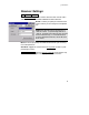
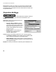
GPS Reference Manual Settings -RE 6HWWLQJV The Settings screen opens several individual screens that control all hardware and software settings. The screens are provided in an index card format. There are two ways to navigate to the various screens. The first method is to tap the button to drop down the list of available screens and then tap on the desired screen from the list to open it.
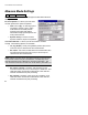
Job Menu Receiver Settings -RE 6HWWLQJV 5HFHLYHU The Receiver Settings card is used to select the GPS receiver make and model as well as the mode of differential data collection. Brand: is where you specify the manufacturer of the receiver you are using from a dropdown list. Note: Many dialogs require connection to a receiver to work. To open dialogs without a receiver, set the Brand to Manual Mode and the Model to Manual Entry.
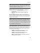
GPS Reference Manual Measure Mode Settings -RE 6HWWLQJV 0HDVXUH 0RGH The Measure Mode card is used to configure the RTK data collection settings. Receiver Dynamics: is where you control the receiver dynamics for point occupations. • Static on occupy: On starting a point occupation, receiver is put in static mode where it calculates position assuming no motion and applies advanced averaging techniques for the most precise solution.
Job Menu Note: All receivers need to be in static mode to record Rx. Raw, and some receivers always record Rx. Raw when in static mode. If the combination of settings you select is not compatible for your receiver, you will be prompted to change the settings.. Accept: is where you control the solution quality acceptable for storing measurements. You have two options: • Fixed RTK only: Allows storage of fixed solution only. • Code, Float, or Fix: Allows storage of any differential solution.
GPS Reference Manual Auto Accept: is where you select to use criteria for automatic point acceptance. When checked, both the data and Offset Shots screens will automatically accept points once the measurement is better than the specified criteria. Projection Settings -RE 6HWWLQJV 3URMHFWLRQ The Projection Settings card is used to define the projection mode you will use to calculate horizontal and vertical coordinates in your survey.
Job Menu Post Process Settings -RE 6HWWLQJV 3RVW 3URFHVV The Post Process card is used to configure the post processing raw data storage settings. Recording Interval: is where you set the period for receiver internal raw data recording. Set it to Off to disable post processing data collection in survey pro and to turn off receiver recording on configuration. RTK Autonomous Points: is where you specify action to take when accepting autonomous points during RTK data collection.
GPS Reference Manual Note: This function only works during post processing data collection using the session screen. For status during simultaneous post processing and RTK data collection, refer to the status screens or the RTK status bar. Receiver Settings -RE 6HWWLQJV 5HFHLYHU 5HFHLYHU 6HWWLQJV« The receiver Settings contains several settings specific to the selected manufacturer and model of receiver. Some of these setting will vary compared to what is displayed here.
Job Menu &KDQJH« : opens the Receiver Communications screen, where many of the displayed communications settings can be changed. Receiver Communication Screen -RE 6HWWLQJV 5HFHLYHU 5HFHLYHU 6HWWLQJV 5HFHLYHU &KDQJH The Receiver Communication card is used to change the settings for communication between the data collector and the receiver. Baud Rate: is where you select the communication baud rate. Note: When you tap 2. , the selected baud rate will only get set in Survey Pro.
GPS Reference Manual $XWR 'HWHFW : checks the receiver at all allowable baud rates to find the current receiver communication settings. If this function succeeds, Survey Pro is set to communicate at the baud found on the receiver. Base Radio Settings -RE 6HWWLQJV 5HFHLYHU 5HFHLYHU 6HWWLQJV« %DVH 5DGLR The Base Radio Settings card is used to view and configure the settings for the radio used with the base receiver. Baud Rate: displays the baud rate the receiver will use to communicate with the radio.
Job Menu Radio Communications Screen -RE 6HWWLQJV 5HFHLYHU 5HFHLYHU 6HWWLQJV %DVH 5DGLR &RQILJXUH 6HULDO -or-RE 6HWWLQJV 5HFHLYHU 5HFHLYHU 6HWWLQJV 5RYHU 5DGLR &RQILJXUH 6HULDO The Radio Communications screen is used to change the settings for communication between the base or rover receiver and the radio. Baudrate: is where you select the baud rate the receiver will use to communicate with the radio.
GPS Reference Manual Radio Settings Screen -RE 6HWWLQJV 5HFHLYHU 5HFHLYHU 6HWWLQJV %DVH 5DGLR &RQILJXUH 0RGHP -or-RE 6HWWLQJV 5HFHLYHU 5HFHLYHU 6HWWLQJV 5RYHU 5DGLR &RQILJXUH 0RGHP The Radio Settings screen is used to configure settings of the base or rover radio mode. All settings available are described below. However, not all radios support all of the described settings, so if you do not see one of these fields, it is because the radio type does not support it. Pac Crest Radio Settings screen.
Job Menu Rover Radio Settings -RE 6HWWLQJV 5HFHLYHU 5HFHLYHU 6HWWLQJV« 5RYHU 5DGLR The Rover Radio Settings card is used to view and configure the settings for the radio used with the rover receiver. It is identical to the Base Radio card described on Page R-14. General Settings -RE 6HWWLQJV 5HFHLYHU 5HFHLYHU 6HWWLQJV« *HQHUDO The General Settings card is used to configure additional settings and to select any receiverspecific settings.
GPS Reference Manual RTK Configurations -RE 6HWWLQJV 5HFHLYHU 5HFHLYHU 6HWWLQJV« 57. &RQILJ The RTK Configurations Settings card is used to configure automatic connection when RTK base and rover receivers need to use different COM ports and settings. Auto connect RTK with saved configuration: is where you turn on the automatic connection function. When selected, this feature will switch to the receiver brand and model and set the port settings to the saved configuration.
Survey Menu – RTK The Survey Menu contains the routines used for collecting data. The screens below are available only when running Survey Pro in RTK mode. The screens available when running in Post Processing mode are described in the next section.
GPS Reference Manual GPS Status 6XUYH\ *36 6WDWXV The GPS Status screen contains several index card-format screens providing information about the current GPS solution. Receiver The Receiver card displays information about the receiver mode and GPS solution quality. Mode: displays if the receiver is set to Off, Base, Rover, or Post Processing mode. Memory: displays the amount of memory remaining in the receiver’s internal storage card. Battery: displays the remaining battery charge in the receiver.
Survey Menu – RTK • Code: we are receiving a code differential solution (precision is about 1 to 10 meters). • Float: we are receiving a carrier phase differential solution with float ambiguities (precision is typically within 0.1_m to 0.5_m). • Fixed: we are receiving a carrier phase differential solution with fixed ambiguities (precision is typically within 15_mm for single-frequency receivers and 5_mm for dual-frequency receivers).
GPS Reference Manual consistently greater than one second, check the radio link. Reception: displays the receiver’s estimation of the percent quality of the radio link. Position Quality: (see the Receiver card on Page R-20.) Sky View The Sky View card displays a plot of the satellites tracked and the elevation mask boundary. Note: If the receiver setup has not yet been performed, the elevation mask will not be displayed.
Survey Menu – RTK Position The Position card displays your current position as well as your course and speed information if you are moving. Position: displays your current coordinates. Solution: (see the Receiver card on Page R-20.) Heading: displays your course over ground if you are moving. Speed: displays your horizontal speed over ground if you are moving.
GPS Reference Manual Base Height: displays the current height of the base point set in Survey Pro. Antenna: displays information about the antenna if it is available. 6HWXS : opens the Base Setup wizard where the base position can be set and the receiver configured for RTK and post processing data collection. &OHDU : (visible only in Manual Entry mode) clears the existing base setup so you edit the point if necessary.
Survey Menu – RTK 1H[W ! : opens the final Base Setup screen. The final screen depends on the base point you choose: • If the base point has existing geodetic coordinates, or if they can be computed from 3D plane coordinates and the latest projection solution, the final screen allows you to SET the receiver with the known position.
GPS Reference Manual Base Point: displays the base point name chosen in the previous screen. Latitude: is where you enter the WGS84 latitude for the base point. Longitude: is where you enter the WGS84 longitude for the base point. Ellipse Height: is where you enter the WGS84 ellipsoid height for the base point. Note: You can enter latitude in dd.mmsssss format with north positive, or you can enter dd mm ss.ssssss N/S. You can enter longitude in ddd.
Survey Menu – RTK Base Receiver Antenna 6XUYH\ %DVH 6HWXS 6HWXS« 6HWXS +5 The Base Receiver Antenna screen is used to define the parameters of the antenna used with the base receiver. Antenna Type: is where you select the model of antenna to use. The options available here depend on the current receiver. Measure To: is where you select method for antenna height measurements. Most antennas have only two choices, measure to bottom of mount, or a visible slant measure mark.
GPS Reference Manual Note: When this screen is used by the RTK rover for updates of antenna height during a survey, the Set button will send the new antenna parameters to the receiver as well as updating Survey Pro's settings. Rover Setup 6XUYH\ 5RYHU 6HWXS The Rover Setup screen is used to configure an RTK rover to begin receiving differential corrections and to start the survey with the base reference position. Rover Status: displays the status of the rover.
Survey Menu – RTK Measured: is where you enter the height of the antenna, measured to the location specified on the Rover Receiver Antenna screen. 6HWXS +5 : opens the Rover Receiver Antenna screen, which is identical to the Base Receiver Antenna screen discussed on Page R-27 where the details of the rover antenna are defined. Note: the antenna information and receiver serial number is stored in the registry.
GPS Reference Manual 6HWXS +5 : opens the Rover Receiver Antenna screen, which is identical to the Base Receiver Antenna screen discussed on Page R-27 where the details of the rover antenna are defined. 3URMHFWLRQ : opens the Projection screen (Page R-37). 9LHZ 3RLQW : opens the View Coordinates File screen, where the project points can be examined. 3RVW 3URFHVV : opens the Receiver Session screen, described on Page R-73.
Survey Menu – RTK Check Control Point Screen 6XUYH\ &RQWURO 3RLQWV &KHFN 3RLQW The Check Control Point screen is used to check a control point. This is done when you want to verify the quality of the local projection setup. Coordinates: displays the local coordinates computed using the current measurement and the latest projection solution.
GPS Reference Manual Occupy Control Point Screen 6XUYH\ &RQWURO 3RLQWV &RQWURO 3RLQW The Occupy Control Point screen is used to add geodetic coordinates for a known project point. The most common use of this screen is to measure control points for the localization solution. This screen is also used by the Localization Calculator routine (Page R-51) for one point localization setup. Geodetic Coordinates: displays the geodetic coordinates measured to the current control point.
Survey Menu – RTK Data Collection 6XUYH\ 'DWD &ROOHFWLRQ The Data Collection screen is used to collect new points for the current job. GPS Status: displays the current solution type, the radio reception quality, the number of satellites used and the horizontal precision computed by the receiver. When this area is tapped, the GPS Status screen (Page R-20) will open. Point: is where you enter the point name for the next point to be stored.
GPS Reference Manual Feature Collection Screen 6XUYH\ 'DWD &ROOHFWLRQ )HDWXUH The Feature Collection screen is used to partially automate the process of data collection. It is useful when collecting data for groups of points that describe the same feature. Note: If you hotkey to another screen while using the Feature Collection routine, the Feature Collection screen will be suspended until you return to it.
Survey Menu – RTK Interval: is where you enter the interval criteria used for continuous collection modes. The Interval field is not available if either of the manual methods is selected. Update Rate: is where you set the receiver to One Hz or Five Hz mode. When Five Hz is selected, the receiver will compute positions five times a second so the display will update in near real time and measurement latency will be minimized.
GPS Reference Manual Slope Dist / Horizontal Dist: is where you enter the slope distance or horizontal distance from the occupied point to the offset point. 6KRRW /DVHU : triggers the selected conventional instrument (laser range finder) to take a shot to the offset. The measurements available from the conventional instrument will return to the distance and zenith angle fields, and if available, the azimuth (horizontal angle). 2FFXS\ *36 : is used to occupy the GPS reference point.
Survey Menu – RTK $FFHSW : returns you to the previous screen, and depending on which screen was used to open the Occupy Data Points screen, will usually store the new point. *36 6WDWXV : stops the epoch counter and opens the GPS Status screen (Page R-20). Projection Screen 6XUYH\ 3URMHFWLRQ The Projection screen is used to select and solve the horizontal and vertical projections.
GPS Reference Manual Mapping Plane 6XUYH\ 3URMHFWLRQ +RUL]RQWDO The Horizontal tab of the Projection screen is explained below for when the horizontal projection type is set to Mapping Plane. Status Line: The lines of text on the top of the screen display the status of the horizontal projection solution. Status will be: • No zone selected: No map projection zone or localized site is set. • Projection zone selected. A map projection from the database is set.
Survey Menu – RTK 6ROYH /RFDOL]DWLRQ« : opens the Solve Localization screen, where the control points can be selected and the horizontal and vertical localization are solved. Note: The Solve Localization screen will do any combination of horizontal and vertical solution when launched from either the horizontal or vertical card. Using the Solve Localization screen to calculate a mapping plane zone localization is very similar to computing a Ground- TDS Localization solution.
GPS Reference Manual 'HOHWH deletes the currently selected site or zone. Note: Delete cannot be undone. Also, you cannot delete system database records. If you select a protected record, you will be prompted that the record cannot be deleted. )LQLVK accepts the currently selected zone, sets the projection record and writes the raw data. Projection Key In Setup 6XUYH\ 3URMHFWLRQ +RUL]RQWDO 6HOHFW =RQH .
Survey Menu – RTK Grid and Azimuth Parameters: is where you select the grid azimuth and the positive coordinate direction. • North Azimuth: is where you set a north azimuth for your new zone. • South Azimuth: is where you set a south azimuth for your new zone. • North/East Grid: is where you set the coordinates increasing positive in the north, east direction • South/West Grid: is where you set the coordinates increasing positive in the south, west direction.
GPS Reference Manual Projection Key In Setup - Oblique Mercator This page is only displayed when the Zone type is set to Oblique Mercator Angle. Azimuth At: is where you enter the convention for projection azimuth. Your choices are: • Equator: • Center of Projection: Origin At: is where you enter the convention for projection azimuth. • Equator: • Center of Projection: Projection Key In Setup - Ellipse The following screen is only displayed when Datum type is Molodensky or Similarity.
Survey Menu – RTK Values: is where you enter the values for the custom ellipse if you are not using Ellipse from List: Ellipse a: is where you enter the semi major axis of the new ellipsoid. Other Parm: is where you select the other ellipse parameter to enter. You can use one of: Semi minor axis; Flattening; Reciprocal flattening; First eccentricity; First eccentricity squared; Second eccentricity; Second eccentricity squared.
GPS Reference Manual the sign of the values before entering into Survey Pro. Projection Key In Setup - Datum from Data Base The following screen is only displayed when Datum type is Pick from Data Base. Datum: is where you select the data base datum to use for the new zone. Projection Key In Setup - Zone Parameters The final screen of the Projection Key In Setup wizard displays the parameters of the user input zone.
Survey Menu – RTK Ground - TDS Localization The Horizontal tab of the Projection screen is explained below for when the horizontal projection type is set to Ground - TDS Localization Status Line: The lines of text on the top of the screen display the status of the horizontal projection solution. If the localization is solved, the name of the site will be displayed. Status of the solution will be one of: • • Localization not Initialized: No default reference stereographic projection has been setup.
GPS Reference Manual Localization Projection Setup 6XUYH\ 3URMHFWLRQ +RUL]RQWDO 3URMHFWLRQ 6HWXS The Localization Projection Setup screen is used to manually configure the parameters of the localization reference stereographic projection. Zone / Site Name: displays the name of the current initialized localization zone or the solved localization site. Setup Group: is where you enter the set up group of the reference stereographic mapping plane.
Survey Menu – RTK Localization Data Base 6XUYH\ 3URMHFWLRQ +RUL]RQWDO 3URMHFWLRQ 6HWXS 3LFN IURP 'DWDEDVH The Localization Data Base screen is used to pick a localization reference stereographic map projection zone or a solve localization site from the database. Data Base: is where you select which records to choose. You can: • View Zones, which will display controls to pick a localization reference stereographic map projection zone.
GPS Reference Manual Solve Localization The user interfaces for mapping plane calibration and TDS Localization are mostly identical. TDS Localization is simply a calibration with a default map projection, initialized for ground measurements, instead of a user selected map projection. This section explains how to solve a horizontal and vertical adjustment in either Mapping Plane or Ground - TDS Localization mode.
Survey Menu – RTK Fix scale to 1.0: Check the Solve Rotation Only control to constrain the least squares solution to a scale of 1.0. Do this when you want to orient your GPS to an existing grid but you want to hold the scale of the GPS measurements. Solution | Solve H: Check Solve H to use the selected control points in a least squares solution or to use the horizontal values from the manual entry card.
GPS Reference Manual A point list of all control points is displayed along with the residual or misclosure for each point (depending on least squares solution or unique solution). You can change the points used in the solution and re-solve on this page to display the new residuals. 6ROYH! : is displayed when the point list has changed. Tapping solve will recalculate the parameters and display new residuals or misclosures for the control point list. 1H[W! : advances the wizard the results screen.
Survey Menu – RTK Vertical Card The Vertical card is used to manually enter the five parameters of the vertical localization solution. Slope N: is where you enter the slope of the inclined plane along the local north grid axis in parts per million. Slope E: is where you enter the slope of the inclined plane along the local east grid axis in parts per million. Separation: is where you enter the separation between the inclined plane and the local elevation.
GPS Reference Manual &DOF 6FDOH : opens the Localization Calculator screen where the horizontal scale factor is explained. Rotation: is where you enter the rotation angle used to transform the orientation of the localization mapping plane to your grid orientation of your project. &DOF 5RWDWLRQ : opens the Localization Calculator screen where the rotation can set parallel to a mapping plane selected from the database. Base Station Local Coordinate: are the local plane coordinates of the base.
Survey Menu – RTK Localization Calculator – Rotation 6XUYH\ 3URMHFWLRQ +RUL]RQWDO 6ROYH /RFDOL]DWLRQ &DOF 5RWDWLRQ In order to compute the localization rotation, you need a known geodetic coordinate system for reference. Use this function to set the localization coordinate system parallel to a selected mapping plane Note: Survey Pro versions prior to 3.5 allowed users to calculate rotation using either a known mapping plane, or relative to the first base setup.
GPS Reference Manual Solve Localization – Results 6XUYH\ 3URMHFWLRQ +RUL]RQWDO 6ROYH /RFDOL]DWLRQ 6ROYH ! or 0DQXDO (QWU\ ! or &DOFXODWRU ! Horizontal Card The Horizontal card shows results of the horizontal localization solution. Status: displays the status of the current horizontal solution. This will be one of the following: • Control points solution: is displayed when the parameters were calculated from the selected control points.
Survey Menu – RTK Vertical Card The Vertical card shows results of the vertical localization solution. Status: displays the status of the current vertical solution. This will be one of the following: • Control points solution: is displayed when the parameters were calculated from the selected control points. • Current vertical site: is displayed when there is a vertical solution and Solve V was not selected on this pass.
GPS Reference Manual Vertical Card 6XUYH\ 3URMHFWLRQ 9HUWLFDO The Vertical card displays information about the currently selected horizontal projection method. If the selected projection method has not yet been set up, many of the fields in this screen will be blank. The buttons on the Vertical card will vary depending on the type of horizontal projection selected. This is set using the Projection Settings screen (Page R-10).
Survey Menu – RTK 6HOHFW *HRLG« : opens the Geoid Model Setup screen, where you can select a geoid to use with the current zone, change the geoid file of the selected geoid, or remove the geoid model from the zone. 6ROYH /RFDOL]DWLRQ« : opens the Solve Localization wizard, where the control points can be selected and the horizontal and vertical localization are solved.
GPS Reference Manual Ellipsoid Height The Vertical tab of the Projection screen is explained below for when the vertical projection type is set to Ellipsoidal Heights. The unaltered ellipsoid heights measured by the receiver will be used for elevations.
Survey Menu – RTK Remote Elevation 6XUYH\ 5HPRWH (OHYDWLRQ The Remote Elevation screen is used to compute and store a new base point elevation and vertical site by occupying a known vertical benchmark at the rover. Note: The Remote Elevation screen is only available when a geoid model is used for the vertical projection and the base and rover are set. Base Point: displays the current base point number and elevation details. Info: displays detailed information about the base point.
GPS Reference Manual $FFHSW : Updates the projection with the vertical solution calculated from the control point observation and updates the base point elevation coordinate. When the horizontal projection is not solved, and the dialog is used only to occupy a vertical control point, the $FFHSW button simply closes the dialog. 2FFXS\ %HQFKPDUN : opens the Occupy Control Point screen (Page R32) where the measurement is taken by the rover on the remote benchmark.
Survey Menu – RTK Receiver Recording 6XUYH\ 5HFHLYHU 5HFRUGLQJ The Receiver Recording screen is used to start or stop the receiver recording. When in RTK mode, it allows you to stop the recording of the base or rover RTK receiver. 6WDUW 5HFRUGLQJ : Opens a file on the receiver’s internal memory and begins recording GPS raw data for post processing.
GPS Reference Manual title of this field changes depending on if the antenna has already been setup. Measured: is where you enter the height of the antenna, measured to the location specified on the Post Processing Antenna screen. 6HWXS +5 : opens the Post Processing Antenna screen (Page R-27) where the details of the base antenna are defined. Receiver Information 6XUYH\ 5HFHLYHU ,QIR The Receiver Information screen is used to display the serial number and firmware version of the current receiver.
Survey Menu – RTK Readjust Points 6XUYH\ 5HDGMXVW 3RLQWV The Readjust Points screen is used to readjust selected points with the latest projection settings. The horizontal and vertical coordinates can be adjusted independently. 7DS 3RLQWV« : opens a map view where you can select points by tapping them on the screen. 7R )URP« : opens the Select Point(s) screen where you can select points by specifying a point range.
GPS Reference Manual Readjust Points: Plane to Geodetic – Screen Two Points Selected: displays the number of points selected. &KHFN ! : calculates the difference between the plane coordinate and the plane coordinate solved with the latest projection for each selected point. Opens the final screen to display the results. 5HFDOFXODWH ! : calculates the plane coordinate with the latest projection for each selected point and updates the point records. Opens the final screen to display the results.
Survey Menu – RTK Readjust Points – Recalculate Results Displays the number of points that were adjusted and if any points were not adjusted, a brief explanation is given. Projection Calculator 6XUYH\ 3URMHFWLRQ &DOF The Projection Calculator is used to calculate scale factor or convergence (rotation) for any point on the selected mapping plane. , Past You can use the computed values for calculations from the Results power button option. Projection: displays the current mapping plane settings.
GPS Reference Manual Projection Calculator – Rotation Convergence: displays the computed rotation from geodetic north to grid north. Rotation: displays the computed rotation from grid north to geodetic north. %DFN : returns you to the first Projection Calculator screen. $FFHSW : copies the two computed values to past results and returns you to the Main Menu. Projection Calculator – Scale – Height Correction Ellipsoid Height: is where you enter the WGS84 ellipsoid height for your current location.
Survey Menu – RTK Projection Calculator – Scale Mapping Plane Scale Factor: displays the computed mapping plane scale factor on the selected mapping plane at the reference point. Ellipsoid Scale Factor: displays the computed ellipsoid scale factor at the reference point. Combined Scale Factor: displays the Mapping Plane Scale Factor multiplied by the Ellipsoid Scale Factor. This is the ground to grid scale factor. Inverse Combined Factor: displays the inverse of the Combined Scale Factor.
Survey Menu – Post Processing The Survey Menu contains the routines used for collecting data. The screens below are available only when running Survey Pro in Post Processing mode. A: GPS Status B: Start Static Rx. C: Start Stop/Go Rx.
GPS Reference Manual GPS Status 6XUYH\ *36 6WDWXV The GPS Status screen contains most of the same index card-format screens as the RTK Status case. When in Post Processing mode, the Post Process card replaces the Data Link card. Post Process The Post Process card displays information about data recording on the receiver and information about the session in progress. Note: Some GPS receivers monitor post processing session status while others simply record event markers in the raw data file.
Survey Menu – Post Processing Remaining: displays the time remaining in the current session if a session is in progress. If your receiver does not monitor sessions, the Remaining field is not displayed. Free Memory: displays the amount of memory remaining in the receiver internal storage card. HDOP: displays the Horizontal Dilution of Precision. It is a measure of the geometrical quality of the solution. DOP has no units and lower numbers indicate better solution geometry.
GPS Reference Manual Rec Interval: the recording interval set on the Post Process card of the Job, Settings screen (page R- 11). Mem. Threshold: displays the memory threshold set on the Post Process card of the Job, Settings screen. SV Threshold: the satellite threshold set on the Post Process card of the Job, Settings screen. HDOP Threshold: displays the HDOP threshold set on the Post Process card of the Job, Settings screen.
Survey Menu – Post Processing screen, which is described on Page R-71, except that the user is not automatically taken to the session page after starting recording. Data Collection 6XUYH\ 'DWD &ROOHFWLRQ The Data Collection menu opens the Receiver Session screen. The Receiver Session screen is also opened after receiver recording is started or from other locations if you are doing simultaneous RTK and post processing data collection.
GPS Reference Manual RTK data collection. If you are storing this point in the receiver file only, then the point control is replaced with a simple edit box titled Site ID. You can pick an existing point name when storing to the receiver only. Description: is where you enter the description for the next static session or stop and go point. Log Until Stop: is where you select to use a Duration or to record until 6WRS is tapped. Duration: is where you enter the session length for the next occupation.
Stakeout Menu The Stakeout Menu contains the routines used to stake existing points and other known locations. A: Stake Points B: Polyline Points C: Stake to Line D: Offset Staking E: Slope Staking F: Line and Offset G: Curve and Offset H: Spiral and Offset I: Show Station J: Store Offset Points K: Stake DTM L: Where is Next Point Items shown in gray all utilize the GPS Staking screen described in the Stake Points section and are otherwise identical to the conventional routines.
GPS Reference Manual Stake Points 6WDNHRXW 6WDNH 3RLQWV The Stake Points screen in used to locate and stake out points in the field from coordinates in the job file. The first two screens of this routine are similar to the conventional method, except that the %DFNVLJKW button is replaced with a 6HWXS +5 button to configure rover antenna and the backsight information is replaced with rover antenna height information. See the conventional Reference Manual for details.
Stakeout Menu Rover is greater than 3 m (10 ft) from the design point. Rover is between 0.3 and 3 m (1 and 10 ft), from the design point. Rover is within 0.3 m (1 ft) of the design point. Go EAST / WEST: displays the distance the rover must move in an east or west direction to reach the design point. CUT / FILL: displays the required cut or fill between the current elevation and the design point. 5 Hz Mode: switches the receiver from One Hz to Five Hz mode.
GPS Reference Manual Note: When Store GPS Raw Data on the Job/ Settings/ Measure Mode card (Page R-8) is set to + Rx. Raw (and / or +OBN for Ashtech) switching from ROVING to OCCUPYING will start a session in the receiver, so you will be prompted for a point name and description. The receiver session will be completed and the measurement stored when you tap 'RQH . The occupation is not stored in the Survey Pro .RAW file if you toggle back to ROVING.
Stakeout Menu Stake to Line – Screen Two The second screen is where measurements take place and the staking directions are displayed. The graphic and display direct you to points on line via the shortest route, a perpendicular offset from the rover to the line. The graphic display will change depending on how close you are to the specified line. The chart below illustrates each screen type. Rover is greater than 3 m (10 ft) from the line. Rover is between 0.3 and 3 m (1 and 10 ft) from the line.
GPS Reference Manual 5 Hz Mode: switches the receiver from one Hz to five Hz mode. When this box is checked, the receiver will compute positions five times a second so the display will update in near real time while you are roving to the point. Note: When you switch from ROVING to OCCUPYING, the receiver will be put back in one Hz mode for maximum precision while staking the point. 2&&83<,1* / 529,1* : switches from ROVING to OCCUPYING mode.
Stakeout Menu 6WRUH : prompts you for a point name and description and stores a point for the current location. Note: When Store GPS Raw Data on the Job/ Settings/ Measure Mode card (Page R-8) is set to + BL,CV and/or + Rx. Raw tapping 6WRUH without first switching from ROVING to OCCUPYING will store the point in Survey Pro only; no base line measurement or receiver session will take place.
GPS Reference Manual Although the graphic portion of the screen is continuously updated, the numeric values are not updated until the 6KRW button is tapped. The correct procedure for slope staking in GPS mode is to use the graphic portion of the screen to locate the catch point as closely as possible and press 6KRW . Once the position is satisfactory, you can determine if the rover needs to be moved again.
Stakeout Menu Note: The Vertical Map will show an X at the location of each previous shot. This can be useful in determining if the current terrain will never intersect the slope (no catch point). • • + 0DS : displays an overhead view of the job. 1 ( = : displays the coordinates computed from the last shot. 2FFXS\« : switches the receiver dynamics to static (depending on settings) and opens the Occupy Data Points screen (Page R-36) where data can be collected for the current point.
GPS Reference Manual VD to HP: is the vertical distance from the rod to the hinge point. HD to CL: is the horizontal distance from the rod to the centerline. VD to CL: is the vertical distance from the rod to the centerline.
Stakeout Menu Show Station and Offset 6WDNHRXW 6KRZ 6WDWLRQ The Show Station and Offset routine allows you to position the rover anywhere near a polyline, a range of points that define a line, or an alignment to see where the rod is located in relation to the selected line.
GPS Reference Manual Note: When Store GPS Raw Data on the Job/ Settings/ Measure Mode card (Page R-8) is set to + Rx. Raw (and / or +OBN for Ashtech) switching from ROVING to OCCUPYING will start a session in the receiver, so you will be prompted for a point name and description. The receiver session will be completed and the measurement stored when you tap 6WRUH . The occupation is not stored in the Survey Pro .RAW file if you toggle back to ROVING.
Stakeout Menu Stake DTM 6WDNHRXW 6WDNH '70 The Stake DTM routine allows you to stake an area and get cut / fill and volume information based on a reference DTM or specified elevation datum. The first screen of this routine is similar to the conventional method, except that the %DFNVLJKW button is replaced with a 6HWXS +5 button to configure rover antenna and the backsight information is replaced with rover antenna height information. See the conventional reference manual for details.
GPS Reference Manual Note: When Store GPS Raw Data on the Job/ Settings/ Measure Mode card (Page R-8) is set to + Rx. Raw (and / or +OBN for Ashtech) switching from ROVING to OCCUPYING will start a session in the receiver, so you will be prompted for a point name and description. The receiver session will be completed and the measurement stored when you tap 6WRUH . The occupation is not stored in the Survey Pro .RAW file if you toggle back to ROVING.
Stakeout Menu C.L.: shows the current station and offset information for the rover location relative to the selected centerline. The type of line segment in the polyline at the current station is also displayed. (This card is only available if the With C.L. checkbox was checked in the previous screen.) Note: Tapping anywhere within the map view will open a larger map view, which provides zoom controls.
GPS Reference Manual Inverse Menu All of the routines available from the Inverse Menu are identical to those explained in the conventional Reference Manual. Cogo Menu All of the routines available from the Cogo Menu are identical to those explained in the conventional Reference Manual. Curve Menu All of the routines available from the Curve Menu are identical to those explained in the conventional Reference Manual.
Index A adjust horizontal / vertical64, 65 antenna height ..............R-72 ASCII............................71, 72 auto detect .........................30 B base receiver antenna ...R-27 base receiver session .....R-73 base receiver setup ........R-71 base setup ......................R-23 get and set ..................R-25 pick base point ...........R-24 baselines.............................53 baud rate ............................89 Bluetooth............................
HARN ...................................5 horizontal datums ...............4 HARN ...............................5 NAD27 ..............................4 NAD83 ..............................4 WGS84 ..............................4 WGS84(1996.0) ................4 horizontal projection23, R-37, R-56 I international datums ..........6 J JOB file ........................71, 72 L Lambert Conformal Conic.11 lat, lng, ht.............................8 localization ...................12, 91 control points..........
Index general card................R-17 receiver card...............R-12 rover radio card..........R-17 RTK config card .........R-18 remote elevation ......28, R-59 rotation.........................49, 50 rover receiver antenna ..R-29 rover receiver setup.......R-72 rover setup .....................R-28 RTK ..........................20, R-19 S scale ....................................50 scale factor ...................10, 12 calculator ........................63 ellipsoid ..........................