
Reference Manual Instruction Manual


37
Receiver Description
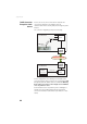
CAN Bus On rear panel. For use in a future release of the product.
5-C Connector, Type: Fischer DPUC 102 A054-130,
protection cap provided.
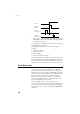
1PPS Output
This output delivers a periodic signal that is a multiple or
submultiple of 1 second of GPS time, with or without offset.
Using the 1PPS output is a standard feature of the receiver
(no firmware option needed).
The 1PPS output is available on port A, pin 7, whatever the
current configuration of this port (RS232 or RS422).
You can set the properties of the 1PPS signal using the
$PASHS,PPS command. These properties are:
• Period: a multiple (1 to 60) or submultiple (0.1 to 1 in
0.1-second increments) of 1 second of GPS time.
• Offset: Amount of time in seconds before (+?) or after (-?)
a full second of GPS time.
5TX+S
6L1
7L2
Pin
Signal Name
Pin
Signal Name
Description
1 NET-SHIELD Shield
2 NET-S Power source (+)
3 NET-C Power source (common)
4 NET-H “High” signal line
5 NET-L “Low” signal line
2
3
1
5
4
1
2
4
3
5