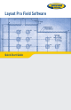
Layout Pro Field Software Quick Start Guide
SOFTWARE END USER LICENSE AGREEMENT (EULA) (TNL - TEBV) IMPORTANT, READ THIS AGREEMENT CAREFULLY. BY INSTALLING OR USING ALL OR ANY PORTION OF THE SOFTWARE, YOU ARE ACCEPTING ALL OF THE TERMS AND CONDITIONS OF THIS AGREEMENT. YOU AGREE THAT THIS AGREEMENT IS ENFORCEABLE LIKE ANY WRITTEN AGREEMENT. IF YOU DO NOT AGREE TO ALL OF THESE TERMS AND CONDITIONS, DO NOT USE OR ACCESS THE SOFTWARE.
2.4. License Restrictions. 2.4.1 You shall not (and shall not allow any third party to): (a) decompile, disassemble or otherwise reverse engineer the Software or attempt to reconstruct or discover any source code, underlying ideas, algorithms, file formats or programming interfaces of the Software by any means whatsoever (except and only to the extent that applicable law prohibits or restricts reverse engineering restrictions).
are non-refundable once paid. You shall be responsible for all taxes, withholdings, duties and levies arising from the order (excluding taxes based on the net income of the Trimble Supplier). Any late payments shall be subject to a service charge equal to 1.5% per month of the amount due or the maximum amount allowed by law, whichever is less. 4. Term of Agreement 4.1.Term.
fessional Services and Trimble, not being a contracting party, has no liability related to such services. 8. Limitation of Remedies and Damages. 8.1.
• 11.3.2. If You obtained this Software outside the U.S., this Agreement is governed by the laws of The Netherlands (country where Trimble Europe B.V., an Affiliate to Trimble, is located), excluding its rules governing conflicts of laws and without regard to the UNCISG. In such case each jurisdiction and venue for actions related to the subject matter hereof are the Dutch courts of the District of Oost-Brabant, The Netherlands, and both parties hereby submit to the personal jurisdiction of such courts.
Data Collector Warranty Program Spectra Precision would like to make you aware of the warranty program. A new data collector that has been purchased and is still under the one year factory warranty or under an extended warranty will be authorized for software updates. Data collectors that are not currently under a warranty plan are eligible to purchase an extended warranty.
Table of Contents Getting Started ..........................................................................1 Working With Jobs......................................................................2 Starting a New Job ................................................................2 Settings and Preferences ............................................................3 Entering a Plan from a Blueprint..................................................4 Entering a Basic Plan....................................
Getting Started Double-tap the Layout Pro icon on the data collector ([1]) or total station ([2]) desktop. With a data collector, the main menu ([3]) will appear instantly. With the onboard version, you will first have to level the total station and enter a few parameters (atmospheric, instrument parameters) before the main menu ([4]) displays. [1] [3] [2] [4] Note: In this guide, all screenshots showing a blue title bar originate from the onboard version of Layout Pro (i.e.
Working With Jobs Starting a New Job 1. Tap Jobs on the main menu. This opens the Jobs menu. 2. Tap Create New Job. 3. Using the keypad, key in a name for the job. The default name is the current date. Change it as you prefer. If you are using a data collector: – Tap to show the keypad – Tap to hide it. 4. Tap ok at the bottom of the screen. 5. Tap OK to continue.
Settings and Preferences From the main menu, tap Settings. The Settings & Preferences window allows you to set: • The instrument used ([1]) (with a data collector) or some instrument-related parameters (atmospheric parameters, calibration, reflectorless target settings) with an onboard version. • The distance units used ([2]) • The format used to display values of distances, angles, etc.
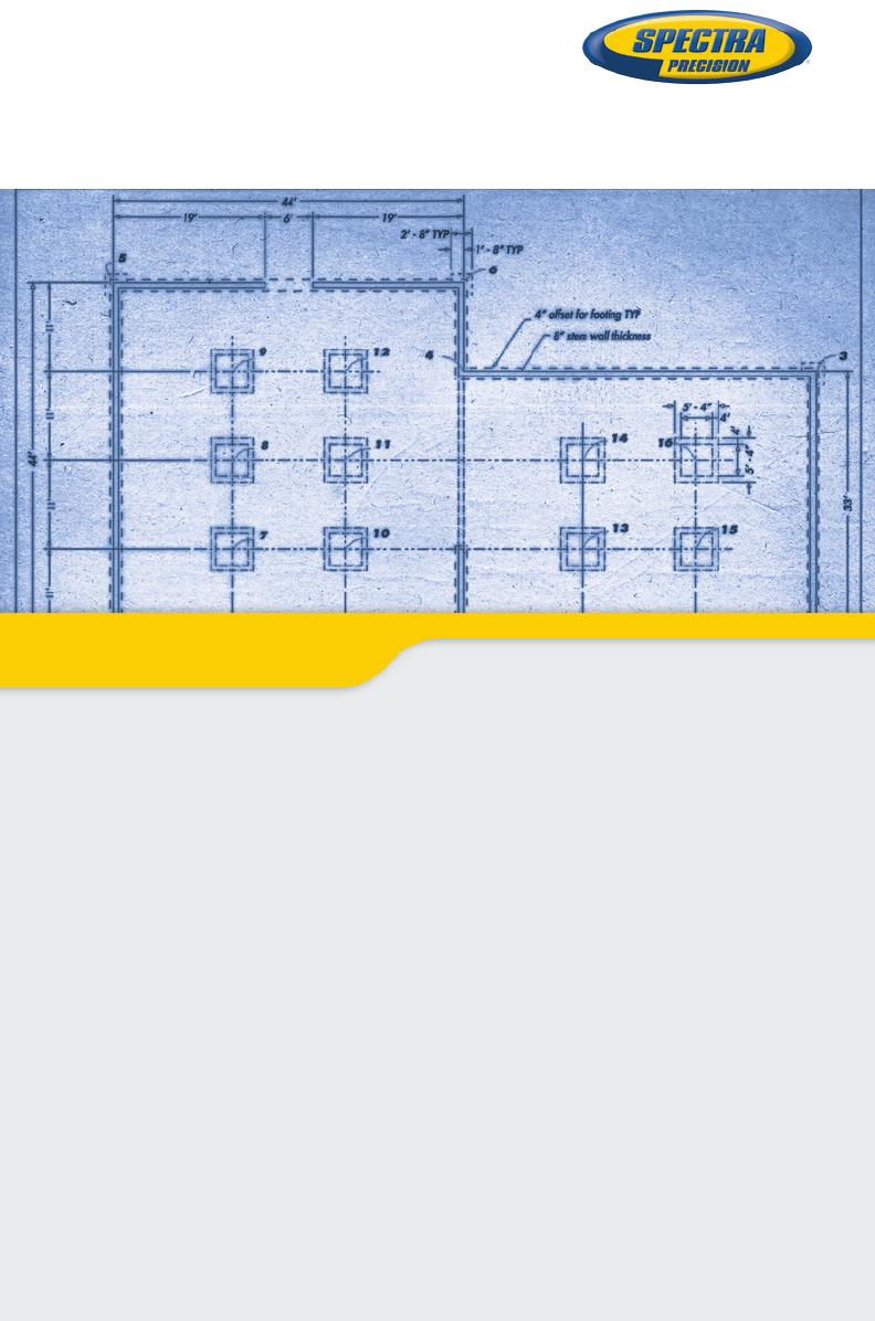
Entering a Plan from a Blueprint Entering a Basic Plan 1. From the main menu, tap Plan. 2. Tap Input Plan to begin entering your plan. The following table shows the tools on the right side of the window that help you work with the display plan. Use this tool... to... Select from plan Show the whole plan Zoom in on active point Zoom out from active point Zoom to select area Set display options for labels (point names, etc.) 3. Enter or select a line start point. 4. Enter the length of the new segment. 5.
Adding an Arc to a Plan B P1 R H A α C P2 1. Select Enter an Arc from the Tools menu located at the bottom of the Enter Line window. 2. Choose the start point (P1) and end point (P2) of the arc. These points can be selected from the plan, or from the list of points, after selecting the corresponding option through the nearby scroll-down arrow button. You can also key in manually their numbers (if known). The selected points will then appear in red on the plan (see below). 3.
– Flip button: Tapping this button provides the other possible orientation for the arc. Tapping again this button will bring the arc back to its initial shape. 8. Tap Solve when you agree with the definition of the arc, which then appears on the plan. See example below. Remember, you can always step back while creating an arc (or a line) using the Back button when shown. Once the arc (or line) has been created, it can be deleted by tapping Undo at the bottom of the screen.
minus sign before the Y coordinate if the point must be located below the horizontal axis (see examples below). • Repeat the previous two steps until all the points have been created. If you make a mistake on entering a new point, tap Undo in the lower bar (the last created point will be deleted) and resume the point creation step. Note that Undo can be used to delete the last three entered points. • After all the points have been created, tap on the Save Pattern button to save the point pattern as a *.
• Tap on the Finish button if you agree (below right), otherwise tap - Example: “2-2” designates the 2nd point in the point pattern anchored to point 2 in the plan. NOTE: The same point pattern may be anchored to different points in the plan, with different rotation values.
Closure Check As you enter the last point from the blueprint, a dialog box appears and asks whether you want to add the point or connect it to an existing point. See example below. To perform a closure check at any time, select Perform Closure Check from the Tools menu. Use the zoom-in tool to see any error which can be caused by a “bust” in the blueprint dimensions or entering the dimensions incorrectly.
3. Set the New lines intersect with existing lines option as follows: – Check it on if you want to create points for every intersection. – Clear it if you want to create points only at the intersections of the lines you specify. 4. Tap Next and define the new lines. For each new line, select the start point and end point directly on the plan. You are then prompted to name the line. The line and resulting new points appear in red on the plan. Create as many lines as necessary. See example below. 5.
Creating Points from an Imported DXF File Introduction You can create points from a DXF file you import into the open job. The points will be part of the open job. After importing a DXF file, the Create Points from DXF function in the Plan menu is made active. This function allows you to view a separate map showing the content of the DXF file on which you can create the points you need, based on the selections you make and the options you choose (see below).
Icon Function Tap on this button to select an arc on the map. Layout Pro then suggests you create a point at the center point of the selected arc. Tap on this button to select a line on the map. Layout Pro then suggests you create a point at either end of the line (line nodes). Additionally, you can create intermediate points on the line between these two points by selecting the Line Nodes and Interval option and specifying the distance between intermediate points (in the Point Interval field).
• Tap to define the elevation of your point(s); (see table above). If you selected a line through can be seen on the screen: , two additional buttons : Allows you to select a line by specifying successively two points to define the line. : Changes the orientation of the selected line. • Tap Next. What happens next depends on which tool you are using (see table above). After you have defined the new points on the map, Layout Pro will ask you to name the point(s). (See example below).
Making Computations from your Entered Plan 1. Tap Plan on the main menu. 2. Tap Compute with Plan on the submenu. 3. Tap in the lower-right corner of the screen. This opens up a menu from which you can perform various computations: 4. Select Compute Area to compute the area and perimeter of a group of points: 5.
6. Select Compute Angle to compute the angle between any three points: 7. Select Compute Down & Out to compute a point’s down and out distance from a line that you specify: The blue line is the reference line. The red section that is overlaid on the blue line is the “down” portion. The red perpendicular line is the “out” portion.
Setting Up a Connected Total Station Before using a total station to perform a stakeout or survey, you must set up your total station (in the location you want to shoot from), level it, and turn it on. If you are using the onboard version of Layout Pro, nothing else needs to be done. If you are running Layout Pro on a data collector, connect the data collector to the total station using a serial cable or Bluetooth. Tolerance & Connection Settings Recommended Settings for Supported Total Stations To 1. 2.
[1] [2] 5. Select Built-in Radio and then enter the radio channel (Radio Channel) and network ID (Network ID) required to communicate with the FOCUS 30. The radio channel and network ID you should type in are those you can read on the FOCUS 30 Face 2 control unit (e.g. Radio Channel=5 and Network ID=9). 6. Tap to enter these two parameters. Wait until the data collector detects the FOCUS 30 and establishes the radio connection. The data collector screen then looks like screen [3] below.
7. Tap ok to return to the Setting & Preferences screen. From this screen, you can now use the Instrument Settings button to access other instrument settings such as instrument name (on General tab), EDM, Lights, Search and Collimation, EDM, Lights 8. Tap ok again to return to the Home screen.
Station Setup If you choose to set up the total station over a marked point from the plan (Marked Points choice, diagram [1] below), you will need to shoot one other point. You may set up the total station on any location either on or off a reference line (Reference Line choice, see diagram [2] below). This method can only be used with no plan entered.
• Tap Next. • Select the point from the plan where to set up the instrument ([1]). Set up the instrument at this location. • Tell Layout Pro whether you want to measure elevation (Yes/No) then tap Next. If you are setting up on a known point and you want to measure elevation, first enter the instrument height, then tap Next. • Select the reference point from the plan ([2]). Have a target placed over this point.
4. If you choose Reference Line, tap Next. Two options are possible: • Either you set up the instrument on the origin of the reference line. (The origin will have been marked on the job site.) You just have to shoot another point of your choice, also located somewhere on the line (see [5] and [6] below). You may measure elevations or not (see below). Tap Finish when it’s done.
Setting the Elevation of the Instrument Location (with instrument located either on or off the line): When selecting the Reference Line method in the Instrument Setup menu, you are first prompted to measure elevation. If you choose “No”, the procedure will be as described above and all measured points will be 2D points, including the instrument point and the marked points.
5. If you choose Any Location (see also diagram below): • Tap Next. • Tell Layout Pro whether you want to measure elevation (Yes/No). If you want to do so, enter the instrument height (as measured from the ground). Then tap Next. • Set up the instrument at any convenient location from which you have a good view of the two reference points. • Select the first reference point from the plan ([15]). Have a target placed over this point.
Performing Stakeout Note: Unless otherwise specified, all the instructions given in this section apply to both mechanical and robotic stations. Whenever found useful, two screenshots are shown side by side, one for mechanical total stations (on the left), the other for robotic total stations (on the right). When a single screenshot is shown, that means there is no significant difference between mechanical and robotic. In that case, the screenshot is shown for mechanical only.
The instrument is always shown at the top of the screen and the green line connecting the instrument to the rod location is always vertical. A blue line with arrow point connecting the rod location to the stake point gives the direction to that point (see example below right). You can also use the tracklight to guide you. Mechanical Robotic 5.
With a robotic total station, you can use the Shoot button to take a measurement (the instrument will switch to whatever EDM mode is set in the instrument settings for this measurement, and then will switch back to Tracking EDM). This will update the “text” guidance information on the screen but will freeze it until the Shoot button is used again. The graphic guidance will, however, continue to be updated as you move to the stake point, based on the measurements made by the instrument.
Stakeout Using a Reference Line 1. When everything is set up correctly (see Station Setup on page 19), tap Line from the Layout menu. 2. Select two points for the reference line on the Layout Pro display. (You may also select an existing line directly to be used as the reference line.) 3. Tap Next. Layout Pro calculates the distance between the two points you selected. The Flip button can be used to reverse the definition of the reference line (AB or BA) 4. Tap Next.
Key in the down and out positions for the point you want to stake.Tap Next. Layout Pro then computes the coordinates of the stake point. With a mechanical total station, rotate the instrument in order to zero the angle to the stake point. When done, the instrument is on line with the point to be staked. Get the rod holder on the same line and tap Shoot to take a measurement. The angle value is shown in bold red on the screen, with right/left direction arrow (see example below left).
Stakeout Using a Reference Arc 1. When everything is set up correctly (see Station Setup on page 19), tap Arc from the Layout menu. 2. Define the reference arc or select an existing one from the plan, using one of the four options below. B P1 R c A [1] P2 P1 [2] P2 P3 P2 P1 [3] • Two points on the arc & radius (see diagram [1]): Select the start (P1) and end (P1) points from the plan, key in the radius (R) and choose the short (A) or long (B) section.
3. Tap Next. You can choose between Stake Out Points and Show Position (see screen below). • If you choose Stake Out Points and tap Next, a screen appears that explains the down and out method of measuring stake points (see screen below). Key in the down and out positions for the point you want to stake.Tap Next. Layout Pro then computes the coordinates of the stake point. With a mechanical total station, rotate the instrument in order to zero the angle to the stake point.
For both types of total stations, complete the procedure as you would for a stake point selected from the entered plan. • If you choose Show Position, no entries are made. Simply take a shot at the rod and the position is shown in relation to the reference arc. See example below.
Measuring Features 1. When everything is set up correctly (see Station Setup on page 19), tap Measure Features from the Layout menu. You may choose to measure either points or a line. 2. Enter a description (if desired) for the line or point being measured. Tap Shoot. The feature is measured and the result automatically stored. 3. Repeat as necessary until all points have been measured. Using Layout Pro Field Software to Import/Export Data Tap Data Center on the main menu.
Layout Pro Field Software Quick Start Guide SPECTRA PRECISION Survey Support: Email: support@spectraprecision.com US & Canada: +1 888 477 7516 Latin America: +1 720 587 4700 Europe, Middle East and Africa: +49 7112 2954 463 Australia: +61 7 3188 6001 New Zealand: +64 4 831 9410 Singapore: +65 3158 1421 China: 10 800 130 1559 Contact Information: AMERICAS EUROPE, MIDDLE EAST AND AFRICA ASIA-PACIFIC Spectra Precision Division 10368 Westmoor Drive Westminster, CO 80021, USA www.spectraprecision.