SM06 TAC/COM SERIES Control Head INSTALLATION AND OPERATION MANUAL REV 4.10 January 4, 2006 Northern Airborne Technology Ltd. 1925 Kirschner Road Kelowna, BC, Canada. V1Y 4N7 Telephone (250) 763-2232 Facsimile (250) 762-3374 Copyright 2005 by Northern Airborne Technology CONFIDENTIAL AND PROPRIETARY TO NORTHERN AIRBORNE TECHNOLOGY LTD.
SM06 Rev. 4.10 Tac/Com Control Head Manual Periodically NAT will release manual amendments. In order to maintain the most accurate and up to date manual these amendments should be carried out immediately upon receipt and recorded on the following amendment record. AMENDMENT RECORD Amendment Amendment Number Date Section(s) Changed Date Entered Entered By Insert any Amendment Instruction sheets after this page. Jan 4, 2006 Page ii ENG-FORM: 820-0110.
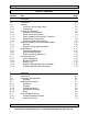
SM06 Rev. 4.10 Tac/Com Control Head Manual Table of Contents Section Title 1 Description 1.1 1.2 1.2.1 1.2.2 1.3 1.3.1 1.3.2 1.3.3 1.3.4 1.3.5 1.4 1.4.1 1.4.2 1.5 1.5.1 1.5.2 1.5.3 1.6 1.6.1 1.6.2 1.6.3 1.6.4 1.6.
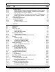
SM06 Rev. 4.10 Tac/Com Control Head Manual Section Title 2.5 2.5.1 2.5.2 2.5.3 2.5.4 2.5.5 2.6 2.7 2.8 2.8.1 2.8.2 Troubleshooting Weak Receive/Transmit, Intermittent Operation, Erratic Squelch Strange Noises, No Receive Audio, Transmit Keying problems Some Frequencies Can't be Edited Display Brightness is Too Low, Can't Increase to Full Brightness Amber (RX) Squelch light comes on, but no RX audio is heard.
SM06 Rev. 4.10 Tac/Com Control Head Manual Section 1 Description 1.1 Introduction This manual contains information on the NAT Tac/Com control heads. All derivative products and interface cards will be covered by manual supplements, which can be obtained from NAT as required. Information in this section consists of purpose of equipment, features and specifications. 1.2 General The Tac/Com control head provides exceptional flexibility and ease of operation while using minimal panel space.
Tac/Com Control Head Manual SM06 Rev. 4.10 The Tac/Com control head carries its own operator's manual in internal software, and can provide on-line help to the operator for all functions. An initial help mode at powerup can provide a complete tutorial of the control head and its operating and storage functions, and pressing the HELP button during either EDIT operation brings up context-sensitive help for the specific storage or data entry function being carried out.
SM06 Rev. 4.10 Tac/Com Control Head Manual Four-Radio Control Heads 1.2.2 Accessories The Tac/Com family encompasses numerous specialized accessories to extend system capability, as well as transceivers and the control heads reviewed in this manual. NAT transceiver capabilities are covered in separate manuals. additional system components include: 1.2.2.1 Remote Mount VHF FM Transceivers *NT030A-xxx *NT030B-xxx *NT136-xxx *NT150-xxx NTX066-xxx NTX138-xxx NTX138E-100 1.2.2.
Tac/Com Control Head Manual 1.2.2.3 SM06 Rev. 4.10 TE12/DTE12/DP12 DTMF Tone Generator/Keyboard Data Entry Unit These devices can output DTMF signalling tones from either keyboard control or stored sequences, and can serve as a direct keyboard data entry system for Tac/Com control heads to change channels and frequencies. Consult NAT Ltd. for further information. 1.2.2.
SM06 Rev. 4.10 1.3 Tac/Com Control Head Manual Purpose of Equipment The Tac/Com series of control heads provides a centralized location for tactical radio control and channelling of up to four independent transceiver systems. Only the Tac/Com II series will be considered; for further information, contact NAT Ltd. Alphanumeric labeling of each radio channel is provided, as well as a display of receive and transmit frequencies, to ease pilot identification of the selected channel on each radio.
Tac/Com Control Head Manual 1.3.1 SM06 Rev. 4.10 Interface Considerations Tac/Com offers direct plug compatibility for replacement of C-962/A and C-722/A control heads (for use with the RT-9600 and RT-7200), including the second audio connector. For USFS applications, Tac/Com provides some additional capability when used with the RT-9600.
SM06 Rev. 4.10 1.3.3 Tac/Com Control Head Manual Radio Capability Increase With Tac/Com Wherever possible, NAT has increased the capability of other transceivers via the Tac/Com control head, and those features are summarized below, compared to the original controls: Feature Stored Channels PL Tones* Tac/Com I Tac/Com II C1000 C962/722 32/56 per Radio 30 Total 32 32 for W.E.D. 1 15 Total 1-4 128 per Radio 38 + 83 DPL 32 for W.E.D.
Tac/Com Control Head Manual 1.3.4 SM06 Rev. 4.10 Master/Slave Configuration One powerful configuration that NAT's Tac/Com controls support is the master/slave configuration. In this configuration, two controls can be active at the same time (flight crew and medical crew, for example), and both can select channels and radios. The extraordinary aspect of this interface is the fact that this interconnect requires only 6 additional wires to give full support to both stations.
SM06 Rev. 4.10 1.3.5 Tac/Com Control Head Manual Frequency Data Considerations Tac/Com controls have an intelligent editor that prevents incorrect data entry when programming frequencies for a given agile radio. VHF radios can receive only valid VHF frequencies; UHF radios only UHF frequencies at the correct intervals, and so on. This greatly eases operator use, and prevents many common pilot errors. The C-1000 permits many types of incorrect entries for radios because of its thumbwheel entry system.
Tac/Com Control Head Manual 1.4 Hardware Design Features & Considerations 1.4.1 General SM06 Rev. 4.10 The Dzus mounted Tac/Com control heads use extremely high quality components, including sealed gold contact switches, gold contact connectors and fully masked, conformal-coated FR4 flame retardant circuit boards. Each unit is fully temperature cycled, life-tested, and then supported with a solid one-year warranty and extensive field support to ensure the best possible customer satisfaction.
SM06 Rev. 4.10 Tac/Com Control Head Manual 1.5 Specifications 1.5.1 Electrical Specifications Input Power: 16-33 Vdc. Current: 0.25 A/LED Control 250 Series 0.35 A/LED Control 350 Series 0.45 A/LED Control 450 Series 0.15 A/LCD Control 400 Series +0.075 A/Interface Card Installed (for all types) +0.250 A/28 Vdc for panel lighting Values above are maximum, display set to full intensity.
Tac/Com Control Head Manual 1.5.2 SM06 Rev. 4.10 Physical Specifications Height Tac/Com Series 250/260 and 350/360 450A 450B and 460B 450/460 Length 6.27 inches (159.3 mm) excluding connector Width 5.8 inches (146.1 mm) Weight 2.2 to 2.9 lbs (1 kg to 1.3 kg) depending on model Mounting Horizontal through-panel Dzus mount. Fits standard opening (5" clearance/5.75" panel width) Requires 3" of rail height (450 series require 4.
SM06 Rev. 4.10 1.5.3 Tac/Com Control Head Manual Environmental Specifications Altitude: Pressurized alt. equivalent to 15,000' Unpressurized alt. equivalent to 35,000' Temperature: -20º C to +60º C Operating -55º C to +85º C Survival Humidity: 90% @ +60º C Vibration: DO-160 category K/P/S, console or panel mounting in both helicopters or fixed-wing. All Dzus fasteners MUST be secured. 1.6 Unit Nomenclature Tac/Com control heads are identified by two groups of numbers.
Tac/Com Control Head Manual 1.6.3 SM06 Rev. 4.10 Display Type TH450 - 2FFNN 00 = LCD Display, Master (Discontinued) 10 = LCD Display, Slave (Discontinued) 50 = LED Display, Master 60 = LED Display, Slave 1.6.4 Above example: LED Master Display Filter/Lighting Suffix Information TH260 - 2ZZ 0 = Yellow/Green LED Filter, or Clear LCD Filter, Natural 28 Vdc lighting. (LCD Standard) 1 = Dark Green LED Filter, NVG-friendly LED 28 Vdc lighting 2 = Dark Green LED Filter, Natural 28 Vdc lighting.
SM06 Rev. 4.10 1.6.5 Tac/Com Control Head Manual Interface-Specific Suffix Information The position of the digit in the code reflects the position of the card in the control. The code position from left to right equals the relevant card position from top to bottom.
SM06 Rev. 4.10 Tac/Com Control Head Manual Section 2 Installation 2.1 Introduction Information in this section consists of: unpacking and inspection procedures, installation procedures, post-installation checks, and installation drawings. 2.2 Unpacking and Inspection Unpack the equipment carefully and locate the warranty card. Inspect the unit visually for damage due to shipping and report all such claims immediately to the carrier involved.
Tac/Com Control Head Manual 2.3.2 SM06 Rev. 4.10 Cautions All audio installations can be severely degraded by incorrect wiring and shielding, and may result in much higher cross-talk, hum, and ground-loop interference. This should be considered when installing audio wiring to and from the specific radio.
SM06 Rev. 4.10 Tac/Com Control Head Manual 2. The interface cards for the RT9600 and RT7200 have different locks from those on the original harness. The tight packaging on the Tac/Com control head does not allow spring locks to be used. The harness locks must be changed to jackscrews to match the Tac/Com connectors before flight. New locking hardware is furnished with the control head when these cards are installed. 2.3.4 Mechanical Mounting Installation should be in accordance with AC 43.
Tac/Com Control Head Manual 2.4 SM06 Rev. 4.10 Post Installation Checks Before the unit is permanently mounted, perform the following functional tests and make any needed adjustments and switch or jumper settings. Ensure that the unit is securely mounted before any flight is attempted. 2.4.1 Voltage/Resistance Checks DO NOT ATTACH THE TAC/COM CONTROL HEAD UNTIL THE FOLLOWING CONDITIONS ARE MET.
SM06 Rev. 4.10 Tac/Com Control Head Manual Make the following performance checks (refer to Section 3, Operation): a) Confirm that the desired radios are installed in the assigned Tac/Com control head slots (this data appears at power-up on the display). If any aspect of the radio assignments is incorrect, or if messages such as 'waiting for slave' appear when there is no slave, etc., the set-up of the control head may be incorrect.
Tac/Com Control Head Manual SM06 Rev. 4.10 2.5 Troubleshooting 2.5.1 Weak Receive/Transmit, Intermittent Operation, Erratic Squelch Ensure all antenna mounts are secure, cleanly grounded, and well terminated. Avoid sharp coax cable bends or crushed coax from tie wraps. Never mount any antenna on a composite surface unless a well-grounded and adequately sized (equal in radius to the height of the antenna) ground plane has been provided.
SM06 Rev. 4.10 Tac/Com Control Head Manual aircraft, such as Aerospatiale airframes, there are two dimmers, one of which MUST be ON for normal daylight flight, to drive engine instruments. If this line is accidentally used, then the display will always be at half intensity. A dimmer must be used that is OFF during normal daylight flying, and ON during night flying for correct control head operation.
Tac/Com Control Head Manual 2.8 SM06 Rev. 4.10 Installation Drawings This section has the complete interconnect drawing set for all installations, both current and previous revisions. Be sure to use the correct drawings for your installation. Any unique notes for a given installation type appear in the relevant Interface Card Supplement and in Section 2.3.5. Consult this section for any information that may apply to your specific installation.
Confidential and Proprietary to NAT
SM06 Rev. 4.10 Tac/Com Control Head Manual Section 3 Operation 3.1 Introduction Information in this section consists of the functional and operating procedures for the Tac/Com Control Heads. 3.2 General To understand the operation of the Tac/Com control, a quick review of basic FM radio operation is helpful here. It is normally a requirement to carry out the following general operations on any FM radio system. 1. 2. 3. 4. 5. Turn the radio on and off. Adjust the receive volume of the radio.
Tac/Com Control Head Manual 3.3 Initial Operation 3.3.1 Power-up Help SM06 Rev. 4.10 Turn the Tac/Com system on by rotating any radio volume control away from the OFF detent position. The software revision number will be briefly displayed, followed by a screen presenting an option for use of the on-line HELP system, as shown below. HE LP=Instruction RADIO=Operation If help is selected (i.e.
SM06 Rev. 4.10 Tac/Com Control Head Manual NAT NT-150 or WULFS RT-7200 (etc.) This is the radio type designated for that transceiver slot in the control head (RT1-4), and will change if either the interface card, the stored software set-up or hardware jumper selections are changed in the control head. This message is to advise what the control head thinks should be in that interface slot.
Tac/Com Control Head Manual 3.4.1 SM06 Rev. 4.10 Radio Specific Controls Radio-specific Controls Radio specific controls allow the general operation and function of each radio to be modified independently. The radios are identified as 'RT1, RT2', etc. to the left of the display, and the line of text continues through the display to connect to the specific controls for that radio on the right hand side of the control head.
SM06 Rev. 4.10 3.4.1.2 Tac/Com Control Head Manual RX (Receive) Volume Control RX Volume Controls The RX volume control is adjusted via the round knob for each radio. Rotating this control fully counter-clockwise to OFF turns the specific radio off. If all controls are OFF, then the control head itself turns off. 3.4.1.3 RX/TX Status Indicator RX/TX Status Next to the volume controls are bi-colour indicators that display TX (Transmit) status or RX (Receive) status.
Tac/Com Control Head Manual 3.4.1.4 SM06 Rev. 4.10 Radio Mode Switch Radio Mode Switch The last radio specific control is the MODE or FUNCTION switch, which varies with the type of radio used. For NT-series transceivers, it selects either NORM or SCAN modes of operation, as specifically defined in the status line. For NT-series transceivers scanning occurs at 90 channels/second/radio, and the following scan modes (defined in the status edit mode) are: LIST (up to a block of 32 channels/list).
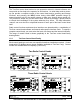
SM06 Rev. 4.10 Tac/Com Control Head Manual The TOP ROW is for NORMAL OPERATION. CHAN RADIO SELECT NEXT EDIT SQ HELP The BOTTOM ROW is for EDITING. To show that they are related, engraved panel lines tie the EDITING functions together. The alternate EDITING functions become active whenever the EDIT switch is in any position other than OFF. 3.4.2.1 Display Switch Display Switch The DISPLAY switch works the same in both NORMAL and EDIT modes of operation.
Tac/Com Control Head Manual 3.4.2.2 SM06 Rev. 4.10 CHAN -/+ Toggle Switch - NORMAL Operation Channel Switch To change channels, press the CHAN switch in the desired direction, either + for ascending, or - for descending numbers. Channel selection can also be accomplished remotely if the remote channelling switch is installed. The radio that has the cursor in front of it is the one that will be channelled. Channel numbers will increase from a02 upwards (a03, a04, etc.
SM06 Rev. 4.10 3.4.2.4 Tac/Com Control Head Manual EDIT Switch Function - NORMAL Operation Edit Switch When the EDIT switch is in the centre-off locked position, all editing functions are off, and the control is in normal operation. It the switch is set to any other position, then editing is active, and either radio or channel data can be altered by the operator. 3.4.2.
Tac/Com Control Head Manual 3.5 SM06 Rev. 4.10 Editing Editing is the general term for changing any information stored in the Tac/Com control head. There are two basic types of editing that can be selected from the front panel of the control head. These are CH (channel) editing, and ST (status) editing. As the name implies, channel editing permits channel data to be controlled by the operator.
SM06 Rev. 4.10 3.5.1 Tac/Com Control Head Manual Channel Editing EDIT Switch When the EDIT switch is in the CH position, the ID, RX, and TX information may be edited. The position or character to be edited will flash or blink on and off. When channel editing of data is in progress, operation of the radios is suspended, and the dual function edit switches work in the following way: 3.5.1.
Tac/Com Control Head Manual SM06 Rev. 4.10 Depending on which way the SELECT switch is set (+ or -), the choices will move around the circle in either direction. The editor removes numbers from this circle that don't apply to the particular cursor position. For example, VHF High Band radios can only have a 3, 4, 5, 6 or 7 in the 10's of MHz position, so no other numbers are permitted during editing from the front panel in this location.
SM06 Rev. 4.10 Tac/Com Control Head Manual Note that a STAR appears at the right side of the RT #2 ID label in the diagram below. This means that the channel discrete line is enabled for that channel. This is a line to control external switching of a special function. It is programmed just like a scan flag, by advancing to that position with the NEXT button, and then toggling the entry with the SELECT switch. There is only one channel discrete line to set, and it appears only for the Flexcomm radios.
Tac/Com Control Head Manual 3.5.2 SM06 Rev. 4.10 Summary of Channel Editing For each channel stored in the control head, there are three possible data entries; identification label (ID), receive frequency (RX) and transmit frequency (TX). If equipped, the radio may also have tone and scan information associated with these entries. Note that non-agile radios can still have frequency data entered in the master edit mode (for reference only), but changing this data will have no effect on radio operation.
SM06 Rev. 4.10 3.5.3 Tac/Com Control Head Manual Summary of Channel Labels Tac/Com permits two kinds of channel numbers (set at installation time) for ease of use and as a memory aid. Block numbers begin with a letter, a-d, and have 32 channels per block. This allows channels to be grouped together for convenience (i.e., all channels for forestry in one block, all EMS in another, all police in another, etc.), and also clearly shows which channels can be scanned together as a group.
Tac/Com Control Head Manual SM06 Rev. 4.10 As soon as the data is loaded into the radio, the next channel in the next block appears (d32). Channels wrap around from highest to lowest, so that it is never necessary to reverse direction to advance to any channel. 3.5.4 Summary of Subaudible Tones Subaudible tones are sometimes used to screen unwanted transmissions on shared frequencies. They are often referred to as PL Tones or Private Line Tones.
SM06 Rev. 4.10 3.5.4.2 Tac/Com Control Head Manual CTCSS or Subaudible Tone Table The following table shows the relationship of the supported tone codes. All of these are available in the control head, and when editing, the SELECT slew switch (+/-) will bring up only valid choices for each type of code. Pressing HELP while editing these positions of the channel data will bring up the tone table for reference. The Frequency shown will have the decimal fraction truncated when displayed on the control head.
Tac/Com Control Head Manual SM06 Rev. 4.10 The additional codes and frequency display were added in the new control head software in 1991 for USFS/OAS contracts. Tone data is often received in the EIA sequential number format, or as the raw frequency, and requires additional tone support for ease of use. Controls with USFS interfaces (guard controls) are set for the EIA sequential tone code at the factory.
SM06 Rev. 4.10 3.6 Tac/Com Control Head Manual Status Line Editing The status lines for each radio contain all the extra functions supported by the radio. Because this is largely defined in software, it also provides a very cost-effective method of upgrading the system performance or features through simple software (EPROM) changes, rather than radical panel re-design.
Tac/Com Control Head Manual 3.6.1 SM06 Rev. 4.10 NEXT and SELECT Switch Use = SIMPLEX TX MODE This choice will cycle with the SELECT switch. This function will cycle with the NEXT switch. Cycling SELECT will change the choice displayed for any given function. To advance to the next function, press NEXT, and it will appear. Use the SELECT switch to again insert the desired option, and continue in this manner until the radio status is correctly defined.
SM06 Rev. 4.10 Tac/Com Control Head Manual To illustrate the choices possible in the STATUS EDIT MODE, the following diagram shows all the current options and choices for an NT-series transceiver. While this appears complicated as a chart, it is very simple to use and just represents a sequence of clear choices that cycle around for user selection. When editing is finished, return the EDIT switch to OFF, and the information will be stored.
Tac/Com Control Head Manual SM06 Rev. 4.10 This is used where the tones are needed only to open the repeater and serve no RX squelch function. 3.6.2.3 POWER= Some radios, such as NAT's NT-series and the RT-9600/7200 support a high and low power transmitter function. Many radio station licenses have power restrictions at altitude, and must be set to low TX power above 5,000' for legal operation. This may also be required to prevent repeater interference at altitude, or to permit secure operations. 3.6.2.
SM06 Rev. 4.10 3.6.2.8 Tac/Com Control Head Manual PWR-UP CHAN= This is the channel the control head will go to when it is powered up. This may be set for each radio. On early Tac/Com I controls, only a specific channel could be set, but current generation Tac/Com I & II motherboards have additional non-volatile memory to remember the last channel used, and so can also provide an option of returning to the last channel set prior to power down.
Tac/Com Control Head Manual SM06 Rev. 4.10 NAT NTX138 radios provide wide-band and narrow-band operation. The bandwidth flag indicates the selected mode. It indicates the current modulation acceptance and transmit deviation mode. When a character is displayed the channel is operating in character is displayed the channel is operating in narrowwide-band mode. When a band mode A typical NTX138 ID line might look like this a01= FORESTRY Channel 3.7.
SM06 Rev. 4.10 3.8 Tac/Com Control Head Manual Changing Display Brightness There is one additional display function, which is the INTENSITY/CONTRAST setting. On LED controls, this is selected by advancing the cursor past the bottom radio. The display brightness screen below will be shown. On a two radio control, simply press the RADIO button two times if the cursor is set to the top radio, or once if set to the bottom radio, and the screen below will appear.
Tac/Com Control Head Manual SM06 Rev. 4.10 approximately 90 channels/second. It takes almost half a second to provide tone or DPL decoding, which would result in virtually useless scanning of 2 channels/second. It is therefore recommended that when using either the NT150 or the NTX138, the tones should be turned off to prevent slow scanning. When Scanning is active, the front panel CHAN switch is inactive (for that radio), because channel control is taken over by the scanning logic in the control head.
SM06 Rev. 4.10 3.9.1 Tac/Com Control Head Manual Scan Modes If priority scan channels are enabled through the status editing mode, the channel label will then be followed by the ident: P1 or P2 viewed in the ID display mode, indicating priority status. If the channel was added to the list scan mode, the SC flag will also be displayed when viewing the channel label. Priority channels are selected by the status line, as is the SCAN MODE (list or priority).
Tac/Com Control Head Manual 3.9.1.3 SM06 Rev. 4.10 LIST+PRIORITY Scanning In this mode, both LIST & PRIORITY features are combined, so that a list can be checked while still periodically testing for activity on two priority channels. This is a new feature and only exists on software revisions 2.13 and later for Tac/Com II, and 1.45 and later for Tac/Com I controls.
SM06 Rev. 4.10 3.11 Tac/Com Control Head Manual Master Edit Mode USE THIS MODE WITH GREAT CARE. SERIOUS PROBLEMS CAN DEVELOP IF THIS MODE IS USED INCORRECTLY, RESULTING IN SEVERE CHANNELING DIFFICULTY. This mode is intended for service related activities, but is presented here briefly for reference, and to aid with any field related data problems. Normally, there is no reason to ever enter this mode unless it is necessary to change a frequency display for some non-agile channel, such as a guard.
Tac/Com Control Head Manual SM06 Rev. 4.10 Anything visible on the screen may now be edited, SO BE CAREFUL!!! If channel numbers are being changed, be sure that they are CORRECT! A mistake here can be very difficult to correct later. IMPORTANT! This mode stays active until the unit is powered down, and is active for ALL RADIOS, not just the one initially selected. Anything that needs to be changed may be fixed, but be sure to power the unit OFF before normal operation.
SM06 Rev. 4.10 3.12 Tac/Com Control Head Manual Installation & Configuration Mode This mode of operation is also not required for normal operation and is intended to aid in servicing and control head set-up. Some firmware functions of the control head can be set via this mode, including the following installation parameters: -Transceiver selection for each interface slot.
Tac/Com Control Head Manual SM06 Rev. 4.10 f) Using the normal editing procedure (SELECT/NEXT), select a valid option for each feature presented. The configuration mode may not be left until all options are completed. g) It is up to you to ensure that the selected options are compatible with each other and with the hardware being used. If they are not, the control head may not operate correctly. Read the following table carefully to ensure that you understand the configuration options completely. 3.
SM06 Rev. 4.10 Tac/Com Control Head Manual FEATURE VALID OPTIONS CHANS. INST. 6, 12, 16, 22, 32, 64, 80, 96, 99, 100, 125, 126, 127, 128 **RT9600 TONES 8, 32 **RT9600 GRD NONE, ST-ED, F/P **NTX MODE FM ONLY/FM & AM **RT9600 P/BW P/BW **NT GRD INST YES, NO **NT136 FM ONLY, AM/FM **CHAN LBL C/H, SPECTRA ** ASTRO TYPE W4, W5, W7, W9 COMMENTS S/W VER.* The number of channels available for each radio. Does NOT include guard channels.