O2iMD1 Intensifier IP® Full HD Megapixel xel Indoor/Outdoor Miniature Dome IP Camera
O2iMD1 User ’s Guide Directions Be careful not to cause any physical damage by dropping or throwing the camera. Especially keep the device out of reach from children. Do not disassemble the camera. No after service is assumed when disassembled. Use only power adapters compatible with the unit. Be careful to prevent moisture or water penetration into the unit. Particular attention is needed when installing the unit.
O2iMD1 User ’s Guide Revision History Date Revision th 1.0 Feb 25 , 2014 Details First manual revision creation. Rev.1.0 (Feb.
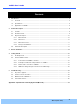
O2iMD1 User ’s Guide Contents 1. 2. Introduction .................................................................................................................................................... 5 1.1. Overview ............................................................................................................................................... 5 1.2. Specifications ..............................................................................................................................
O2iMD1 User ’s Guide 1. Introduction 1.1. Overview The ONSIP O2iMD1 is a state-of-the-art mega-pixel, dual-codec (H.264, MJPEG) IP/network camera built with embedded software and hardware technology. It enables real time transmission of synchronized video of Full HD resolution and audio data. Remote clients can connect to ONSIP O2iMD1 for the real time video/audio data through various client solutions running on PC, PDA or mobile phones.
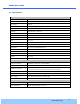
O2iMD1 User ’s Guide 1.2. Specifications Camera Image sensor Progressive scan 1/3 inch CMOS 2M pixels Full resolution 1,920 x 1,080 pixels (Full HD) Sync System Internal Lens 2.9mm fixed (3.6mm, 6mm optional) Day & Night AUTO, DAY, NIGHT Sensitivity Intensifier Max – 0.0005 Lux Back Light Compensation ON / OFF White Balance ATW(2.
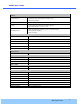
O2iMD1 User ’s Guide Network Network Protocol - IPv4, TCP, UDP, IGMP, ICMP, ARP, RARP, PPPoE, RTCP - RTP, RTSP, SDP, HTTP, SMTP, FTP, DHCP, UPnP - NTP, DNS, DynDNS Dynamic IP Speco DDNS (free of charge) Security - User ID & Password protection, IP address filtering - Digest Authentication, User Access Log Streaming method - RTSP streaming with proprietary format for control information - standard RTSP streaming - HTTP streaming External Terminals LAN 10/100BaseT LAN (auto MDIX) Analog output 1
O2iMD1 User ’s Guide 1.3. Applications of O2iMD1 Security surveillance (buildings, stores, manufacturing facilities, parking lots, banks, government facilities, military, etc.) Remote monitoring (hospitals, kindergartens, traffic, public areas, etc.) Teleconference (Bi-directional audio conference). Remote Learning, Internet broadcasting Weather and environmental observation Rev.1.0 (Feb.
O2iMD1 User ’s Guide 2. Product Description 2.1. Contents The product package contains followings : Contents O2iMD1 Description Remarks O2iMD1 main unit Screws (1 type), Anchors (1 type) Accessories L-type type wrench, wrench CVBS Cable CD Reference Guide Software & User’s Guide Quick installation guide, guide Guide pattern 2.2.
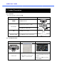
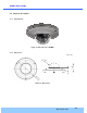
O2iMD1 User ’s Guide 2.3. Physical description 2.3.1. External View Figure 2-1. External view of O2iMD1 2.3.2. Dimensions Unit : mm Figure 2-2. Dimensions Rev.1.0 (Feb.
O2iMD1 User ’s Guide 2.3.3. External Connector Sensor Input: white(+), Red(-) Relay Output: Black(+), Yellow(-) Line Output Network (LAN) Power Mic/Line Input Figure 2-3. Connector for external connection 2.3.4. Factory Default Switch Factory default switch is provided for returning the IP camera to factory default state. Unscrew the cover to access the switch. There are two functions assigned to factory default switch. 1.
O2iMD1 User ’s Guide 2.4. Functional Description Power : Power input for supplying 12V DC power. Caution : If O2iMD1 is powered by PoE, do not plug in DC Jack with active DC power into DC power connector. Network (LAN) 100Mbps Ethernet connector (RJ-45) 45) with PoE standard ((IEEE 802.3af). Micro SD Card slot Please insert SD memory card when you want to use SD memory card. In case of pulling out SD memory card, please push the SD card.
O2iMD1 User ’s Guide Sensor Input Connect external alarm sensor. Examples of sensing devices are infrared sensor, motion sensor, heat/smoke sensor, magnetic sensor, etc. Connect the two wires of the sensors to “Sensor Input”. The sensor type (NC/NO) can be set in admin page. Multiple sensor devices can be connected in parallel. NO/NC Type Photo Coupler Open Collector Type Sensor1+ Sensor Device Sensor Device Sensor1- +12V GND Sensor Power Supply Sensor Power Supply Figure 2-6.
O2iMD1 User ’s Guide 3. On Site Installation Use cables and conduits that are suitable for the installation. Particular attention should be paid in the installation so that no moisture is allowed to penetrate into the unit through the cables or conduits during the life time of the product. uct. Products of which the internal parts are exposed to moisture because of improper installation are not covered by warranty 1. Remove the top cover. 2. Fix the base on the wall. 3.
O2iMD1 User ’s Guide 4. Getting Started Brief information for first time operation of O2iMD1 is provided in this chapter. 4.1. PC Requirement Audio/Video streaming data received from O2iMD1 can be displayed or stored in a PC running client programs.
O2iMD1 User ’s Guide 4.2. Quick Installation Guide 4.2.1. Connect PC and O2iMD1 to network. 1. Prepare a PC to run programs for the installation and video connection (PC is needed to assign IP address to O2iMD1) 2. In the case of using PoE,, connect the PC and O2iMD1 to the network using one of the following ways. If your LAN Switch does not support standard PoE, connect O2iMD1 as shown in dotted line in Figure. Figure The DC power is applied through DC adapter.
O2iMD1 User ’s Guide Follow the sequence below for setting the IP parameter i) Run ONSIP installer ii) Click (1) in ONSIP installer window.> Double click on (2) > Fill in (4) > make a selection in (5) > Fill the parameters in (6) iii) Click on (9) to apply the settings. iv) You can connect to o admin page by clicking on (10). 3 1 2 9 10 5 4 7 6 8 Click on the field in (3) for sorting and rearranging the list. Select network mode that best suits from the drop down list in (5)..
O2iMD1 User ’s Guide 4.2.3. Remote video connection to O2iMD1 1. Connection through Web Viewer Web Viewer offers simplest way of video connection to O2iMD1.. For video connection, enter the IP address of O2iMD1 in the URL window of Internet Explorer as: Default port 80 can be omitted [e.g.] Port 80 [e.g.] Port 8080 Note : Active-X X module should be installed on your PC before actual connection. If your PC is not connected to the internet, you cannot download Active-X Active X module.
O2iMD1 User ’s Guide 2. Connection through Speco-NVR Click the camera assignment button for setting the camera address. Input the description, address, Ch#, User ID, Password and port and then click the save button. After assignment procedure, you must click the SAVE button. You can see the live video when you click the live view button as below. When you exit Speco-NVR, NVR, you have to input the ID/PW, admin/1234. Details for Speco Speco-NVR NVR can be found in [Speco-NVR User’s Guide].
O2iMD1 User ’s Guide 4.2.4. Additional settings through connection to the Admin Page All parameters of the camera are factory default out of the box. For a more sophisticated target application, parameters need to be changed through the admin page. The admin page can be connected through “http://IP_Address:Port_Number/admin.htm” ID and password of the administrator are required. Default ID and password are “admin”, “1234”.
O2iMD1 User ’s Guide 5. Troubleshooting 5.1. No power is applied In case of Standard PoE (Power over Ethernet) Power supply through standard PoE is possible only when the following conditions are met. 1. Standard PoE is supported on the product. 2. The LAN switch supports standard PoE. Make sure that both the IP camera and the LAN switch support standard PoE (IEEE 802.3af) In case of DC adapter If PoE is not applied, the power and network connection should be made through separate cables.
O2iMD1 User ’s Guide 5.2. Cannot connect to the Video Check the status of the network connection through PING test. Try the following on your PC : - Start > Run > Cmd > Ping IP address (Ex : Ping 172.16.42.51) - If “Reply from ~” message is returned ( ① in the figure below), the network connection is in normal state. Try connection to the video again. If the problem persists, or refer to other trouble shooting notes. - If “Request timed out” message is returned.
O2iMD1 User ’s Guide 5.3. Windows Vista or Windows 7 Windows Vista and Windows 7 users need to configure UAC (User Access Control) and Privilege Level for proper recording and still video capture in Speco-NVR Speco and Web Viewer. 1. UAC (User Access Control) configuration 1) Double-click click “User Accounts” in control panel 2) Double-click click “Turn User Account Control on or off” 3) Uncheck “Use UAC to help protect your computer” 2.
O2iMD1 User ’s Guide 1.
O2iMD1 User ’s Guide 2.
O2iMD1 User ’s Guide 5.4. Technical Assistance If you need any technical assistance, please contact technical support.. For immediate service please provide the following information. 1. Model name 2. MAC address and Registration number 3. Purchase date 4. Description of the problem 5.
O2iMD1 User ’s Guide Appendix A – Important Notice in Exchanging SD Card (Micro SD) SD Card is a non-volatile memory device for storing video and audio data on the product. Note that continuous recording to the SD Card will cause the memory cell to wear out, eventually resulting in failure. When you plug out the SD Card for replacement or other purpose, follow the steps below in order to prevent data loss or crash of the SD Card. 1. Press factory default button for 1 sec to unmount the SD Card .