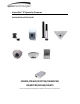
Intensifier® IP Specialty Cameras QUICK INSTALLATION GUIDE O2iBD3/O2i695/O2iTC23/O2i605CM/ O2i607CM/O2i562/O2i675 Please read this guide carefully before installation and operation of the product.
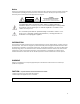
Notice Thank you for purchasing this product. This guide is designed to be a reference tool for the product. Please read it carefully before operating the product and retain it for future reference. Should you require any technical assistance, please contact Speco Technologies Technical Support. CAUTION CAUTION RISK OF ELECTRIC SHOCK DO NOT OPEN TO REDUCE THE RISK OF ELECTRIC SHOCK, DO NOT REMOVE THE COVER (OR BACK). NO USER SERVICEABLE PARTS INSIDE. REFER SERVICING TO QUALIFIED PERSONNEL.
PRECAUTIONS Please read the manual carefully before the installation in order to set up the camera correctly and to obtain the best picture quality. Installation and services should only be carried out by an authorized personnel according to local safety regulations. If any liquid or solid matter gets into the housing, immediately disconnect the camera from power supply and have it checked by your authorized dealer before reusing. Avoid installing the camera in extremely hot or cold places.
1. PRODUCT OVERVIEW Key Features 2.0 Mega pixel 1/2.8" SONY progressive scan CMOS image sensor for excellent image quality Specialty housing design for specific applications 2.9mm wide angle lens or 3.6mm pinhole lens (for O2i562 only) Support for corridor view (in H.
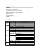
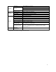
Dynamic IP Network System Integration Physical Security Supported Protocol Intelligent Video Alarm Trigger Video Buffer Firmware Upgrade Etc Memory Slot Power Source Power Consumption Main Unit Weight Main Unit Dimensions Housing Weight Housing Dimensions Environment Operating Temperature SPECO DDNS (Free of Charge) Password protection User access log HTTPS encryption HTTP, HTTPS, DNS, RTSP, RTP, TCP, UDP, ICMP, DHCP Motion detection 12 x 12 blocks Motion detection, External Input (NO / NC Type) 5MB p
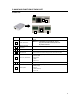
2. NAME AND FUNCTION OF EACH PART 2.1 Main Unit 1 2 3 4 6 5 NO. ITEM 7 DESCRIPTION 1 Power Connector DC12V Caution : If O3FB56M is powered by PoE, do not plug in DC Jack with active DC power into DC power connector.
Sensor Input Connect external alarm sensor. Examples of sensing devices are infrared sensor, motion sensor, heat / smoke sensor, magnetic sensor, etc. Connect the two wires of the sensor to “Sensor Input”. The sensor type (NC/NO) can be set in camera setup after logging in. Multiple sensor devices can be connected in parallel. SENSOR input and connection of the sensor Relay Output Relay output is provided for connecting alarm devices or for remote on / off control of devices such as light.
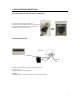
3. INSTALLATION & CONNECTION 3.1 Install Camera Housing and Connect to Main Unit ① Install camera housing as necessary first. the cable from the camera to the main unit. ③ Main unit will provide power to the camera unit. ④ Install the main unit out of reach. ② Connect 3.3 Install Micro SD Card SD Card SD card Slot ① Make sure the contacts are facing up on the Micro SD card. the card. ③ Push until the card clicks into place. ② Insert a.
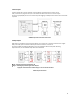
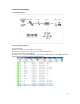
3.4 INSTALLATION EXAMPLE 3.4.1 Installation Example LAN Switch Local Access Router Internet Remote Access E-Mail E / FTP 3.4.2 Connecting to the Network Open up IP Scanner. IP Scanner can search for the device on the local network. Please note that only devices that are on the same subnet can be discovered. The device is set to DHCP mode by default. In the device list, you can view the IP address, model number, and MAC address of each device.
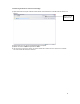
3.4.3 Accessing the Camera or video server’s Homepage 1) Open the browser and input network camera address in the address bar or double click the device in IP Scanner. Input your IP address here 2) Please input your user name and password when prompted. 3) Default user name is admin and password is 1234. 4) The first time you login to the camera, you will be notified that a ActiveX control is required to be installed. You need to allow the installation of ActiveX.