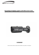
Intensifier® IP Bullet Camera with Motorized Lens QUICK INSTALLATION GUIDE O2iB68M Please read this manual carefully before installation and operation of the product.
Notice Thank you for purchasing this product. This guide is designed to be a reference tool for the product. Please read it carefully before operating the product and retain it for future reference. Should you require any technical assistance, please contact Speco Technologies Technical Support. CAUTION CAUTION RISK OF ELECTRLC SHOCK DO NOT OPEN TO REDUCE THE RISK OF ELECTRLC SHOCK, DO NOT REMOVE THE COVER (OR BACK). NO USER SERVICEABLE PARTS INSIDE. REFER SERVICING TO QUALIFIED PERSONNEL.
Avoid installing the camera at extremely hot or cold places. If you are not a certified person, never try to dismantle the camera. To avoid electric shock, never remove the screws or covers. There are no parts inside that need maintenance by the user. All maintenance should be carried out by qualified personnel. Avoid installing the camera at a place of high humidity. Avoid installing the camera at the place exposed to gas or oil.
Up to 30 frames per second at all image resolutions Supports image resolutions Full-HD (1920 x 1080) Integrated motion detection with pre- and post-alarm image / video buffering Supports CBR (constant bit rate) and VBR (variable bit rate) modes Supports Tampering-Alarm in VA (video analytics) function Controllable frame rate Full Duplex Two-Way Audio support External microphone input & speaker output connectors Video access through any standard Web browser Privacy Masking up to 8 areas
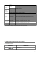
Output Security Network Supported Protocol System Integration Physical Environment Software Package Intelligent Video Alarm Trigger Video Buffer Alarm events Firmware Upgrade Etc Memory Slot Power Source Power Consumption Net Weight LED's Dimension(mm) Operating Temperature Storage Temperature Included Software Package Contents Password protection User access log HTTPS encryption HTTP, HTTPS, DNS, RTSP, RTP, TCP, UDP, ICMP, DHCP, SNMP, IP-FILTER Motion detection 12 x 12 blocks Motion detection, Externa
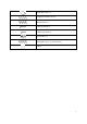
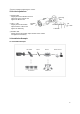
Installation Guide x 1 Tapping screw (Ø4 x 30) x 4 Plastic anchor x 4 L-Wrench (4mm) x 1 L-Wrench (2.
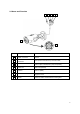
2.2 Name and Function 1 2 3 4 5 6 7 NO. ITEM DESCRIPTION 1 Power Connector DC12V 2 Network and POE Connector POE (Power Over Ethernet) and LAN cable 3 Sensor In / Alarm Out Sensor Input : White(Sensor_In), Yellow(GND) Alarm Output : Black(Alarm_Out), Red(COM) 4 Audio-Out Audio Out (WHITE) 5 Audio-In Audio in (RED) 6 Lens 2.7 ~ 12 / 5.
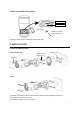
2.3 OSD cap detailed description SD Card Factory Reset Closing Cap L-Wrench (2.5mm) Closing Cap Open Open the Closing Cap and fasten the Closing Cap well. 3. INSTALLATION 3.1 How to mount to wall Wall_Junction Box Tapping screw (Ø4 x 30) x 4 Plastic anchor x4 Screw x 4 Wall ① Drill four screw holes on the wall plate to fix four plastic anchors (supplied) in the holes. ② Fix the plastic anchors in the holes. ③ Position the bracket on the screw points.
④ Fix the bracket by tightening the screws. 3.2 3-Axis Adjustment ① Panning 360˚ Slightly loosen Pan Bracket nut then adjust pan of the camera and tighten the Bracket nut. ② Tilt 0˚ ~ 100˚ Slightly loosen Tilt bolt then adjust tilt of the camera and tighten the bolt firmly. Panning 360° Rotation 360° Rotation Tilt Pan Tilt 0°100° L-Wrench ③ Rotation 360˚ Slightly loosen Tilt bolt then adjust rotation of the camera and tighten the bolt firmly. 3.3 Installation Example 3.3.
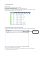
3.3.2 Connecting Network Open up IP Scanner. IP Scanner can search for the device on the local network. Please note that only devices that are on the same subnet can be discovered. The device is set to DHCP mode by default. In the device list, you can view the IP address, model number, and MAC address of each device. Select the applicable device and double click to open up the web viewer. 3.3.
4.