User’s Guide (Ver. 2.1) Models: D8HT/D16HT 8/16 Channel HD-TVI & IP Full Hybrid DVR About This User’s Guide Before operating the unit, please read this user’s guide thoroughly and retain it for future reference.
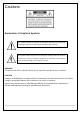
Cautions Explanation of Graphical Symbols This symbol indicates the presence of important operating and maintenance (servicing) instructions in the literature accompanying the product. This symbol indicates the presence of “dangerous voltage” within the product’s enclosure that may be of sufficient magnitude to constitute a risk of electric shock, property damage, personal injury, or death. WARNING To reduce a risk of fire or electric shock, do not expose this product to rain or moisture.
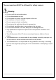
These precautions MUST be followed for safety reasons Warning Do not use if the unit emits smoke. Do not disassemble the unit. Do not place any heavy or sharp objects on the unit. Do not place on uneven surface. Do not expose to shock or vibration. Do not move the unit when the unit is powered on. Do not block, and allow dust to accumulate in the air vents. Do not restrict airflow of the unit; doing so can damage the unit.
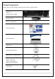
Product Components Please make sure the following components are included as specified below. DVR Unit Desktop: D8HT / D16HT Remote Control Battery 1.5V (AAA x2) Quick Setup Guide Quick User Guide USB Mouse Software & Manual CD Rack mount (x 2) & Screw (x 6) Adaptor (D8HT : DC12V 5A, D16HT : DC12V 6.
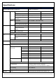
Specifications MODEL NAME D8HT D16HT Operational Mode (HD-TVI, Analog, IP) Flexible for all channels Video HD-TVI Up to 8 Up to 16 Analog Up to 8 Up to 16 IP Camera (Throughput) 8 (40Mbps) 16 (40Mbps) IP Camera Highest Max. 2592x1944 (5MP) Max. 2592x1944 (5MP) Input Resolution Output Audio Input Main Monitor VGA and HDMI (Max.
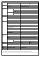
Backup Storage Multi-Decoding 1, 4, 8 Playback Speed x0.25, x0.5, x2, x4, x8, x16, x32, x64 Media USB drive, External HDD, Network File Format BMP, AVI, Proprietary Format Huge Backup Yes (Max.
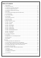
Table of Contents 1. Main Features ............................................................................................................................... 9 2. Initial Boot-up Process................................................................................................................. 10 2-1. Initial Boot up and Basic Time Setup ........................................................................................ 10 2-2. Setting up Daylight Savings Time .............................
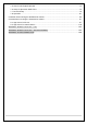
7-5. Search and Playback Window.................................................................................................. 72 7-6. Setup of SpecoTech Multi Client ............................................................................................... 74 7-7. Remote Setup .......................................................................................................................... 79 7-8. Operation ....................................................................................
1. Main Features Easy Record, Copy and Setup Easy Search by Thumbnail Preview Easy Network Easy IP Camera Setup Recording Rate: D16HT: 480fps @ up to 1920 x 1080, D8HT: 240fps @ up to 1920 x 1080 Digital Deterrent, audio message output upon event H.
2. Initial Boot-up Process 2-1. Initial Boot up and Basic Time Setup 1. During the first boot up, the following logo will be displayed. 2. After SPECO booting logo, select your language and set the new password.
2-2. Setting up Daylight Savings Time To enable Daylight Saving feature/NTP synchronization, take the following steps. 1. Enter the SETUP mode. The defaults Username is “admin”, and enter your password set before. 2. Go to Setup > System > Date & Time Setup 3. Select the Daylight Saving on dropdown menu.
2-3. Setting NTP (Network Time Protocol) 1. Setup > System > NTP Setup > on 2. Select your GMT Time Zone refering to the below GMT Time Zone list. Table2.3.1.
GA Georgia GMT-5 GMT-4 HI Hawaii GMT-10 NA ID Idaho (N) GMT-8 GMT-7 ID Idaho (S) GMT-7 GMT-6 IL Illinois GMT-6 GMT-5 IN Indiana GMT-5 GMT-4 IN Indiana (SW / NW) GMT-6 GMT-5 IA Iowa GMT-6 GMT-5 KS Kansas GMT-6 GMT-5 KS Kansas (W) GMT-7 GMT-6 KY Kentucky (E) GMT-5 GMT-4 KY Kentucky (W) GMT-6 GMT-5 LA Louisiana GMT-6 GMT-5 ME Maine GMT-5 GMT-4 MD Maryland GMT-5 GMT-4 MA Massachusetts GMT-5 GMT-4 MI Michigan GMT-5 GMT-4 MI Michigan (W) GMT-6
SD South Dakota (W) GMT-7 GMT-6 TN Tennessee (E) GMT-5 GMT-4 TN Tennessee (W) GMT-6 GMT-5 TX Texas GMT-6 GMT-5 TX Texas (W) GMT-7 GMT-6 UT Utah GMT-7 GMT-6 VT Vermont GMT-5 GMT-4 VA Virginia GMT-5 GMT-4 WA Washington GMT-8 GMT-7 WV West Virginia GMT-5 GMT-4 WI Wisconsin GMT-6 GMT-5 WY Wyoming GMT-7 GMT-6 NOTE: If you want the unit to automatically synchronize the local time, the Time Zone must be properly set according to your local time zone.
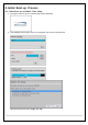
2-4. EZ Setup Quick installation menu for HT and IP Camera Easy installation(Right-Click on the main screen) Figure 2.4. EZ Setup Screen 2.4.1. Setup IP Camera configurations. 1 2 3 4 Figure 2.4.1. EZ CAMERA Setup Procedure ① Select EZ Camera for IP camera setup, Click “next” to proceed. ② Configure individual cameras in the EZ Camera Setup. Select the Channel to configure. Select the Camera Protocol, and then click “select” on Scan menu.
2.4.2. EZ Network (Using an internet connection) 1 2 3 Figure 2.4.2. EZ Network setup procedure ① Select EZ Network for Network Setup. ② DVR will automatically acquire an IP address. ③ DVR will create a default DDNS address, which can be customized with the “Edit” button. ④ Click “finish” to save the setup. 2.4.3. EZ Network setting (Not using internet connection) 1 2 3 4 Figure 2.4.3.
① Select EZ Network for network setup. ② Select Auto Configuration(DHCP) or Manual Configuration(STATIC) and then click “test” button when ready. ③ Input the Network Settings if Manual Configuration(STATIC) was selected, and click “test” ④ Click “finish” to save the setup. 2.4.4. EZ Record Setup 1 2 3 4 5 Figure 4.2.4. EZ Record Setup Procedure ① Select EZ Record for Date/Time and Record Setup, Click “next” to proceed. ② Description of EZ Record Setup is displayed; Click “next” to proceed.
2-5 . IP Camera Setup (through SpecoTech Web Viewer) HT Series allows remote access to the IP Cameras through "IP Camera Setup" menu in SpecoTech Web Viewer. ① Select IP camera channel and click the right button of mouse ② Select “IP Camera Setup”. ③ Enter ID and Password of the connected IP camera ④ It launches the camera’s web setup page.
3. Front and Rear Panels 3-1. Front Panel HT Desktop Front Figure 3.1.1. DVR Front panels Table 3.1.1. Front LED and Ports of Desktop Models (D16HT/D8HT) Name POWER HDD USB Port Description LED light is on when power is applied to the system. LED light is on when the system is recording video data. This USB port for archiving footage into a USB device. (USB 2.0 connector) Table 3.1.2.
3-2. Rear Panel Connectors Do not power this system on before all the connections are attached. Make sure all the connections are properly secured. Faulty connection may result in the system being damaged. D16HT D8HT Figure 3.2.1. Connectors ① GROUND: Use for ground port. ② VIDEO IN: Video input port.(For HD TVI & Analog 960H cameras) ③ VIDEO OUT: MAIN – Composite Video Output / SPOT – Spot Monitor ④ AUDIO IN & OUT: Four connectors for audio input and one connector for audio output.
3-3. Remote Control ① ID: To set the remote control ID. ② REC: To start and stop manual recording ③ SEARCH: To go to SEARCH menu. ④ F/ADV: During playback – To move the playback position 60 seconds forward . During Pause – To move the playback position moves 1 frame forward ⑤ F/REW: During playback – To move the playback position 60 seconds back. During Pause – To move the playback postion 1 frame back. ⑥ FF: To fast forward the recording.
4. Setting up the DVR The following sections detail the initial setup of the DVR. Menu screen will close if user response is not received in 5 minutes. 4-0. Setup – Main Live Screen To enter the setup menu, right click on the mouse and select setup from the submenu or press the setup button on the remote control. Table 4.1.1. Live Screen and Quick Operation Window When the DVR prompts the LOG-IN window, enter the PASSWORD using the virtual keyboard, or the front panel, or the remote control.
4-1. Setup – IP Camera Press the Setup button and enter the password. The setup menu is displayed as picture below. Select IP Camera icon and press “select” button to enter the setup menu item. Figure 4.1.1 IP Camera mode setup screen Table 4.1.1.
IP Address: Enter the address of IP camera to connect, or select from scanned list. Stream Port: Enter the port number of IP camera to connect Web Port: Enter the web port number of IP camera to connect Others Protocol Select the protocol for the IP Camera. (SPECO / ONVIF / HIKVISION) Scan Searches the network for IP Cameras using the specified protocol. IP Address Enter the IP Address of the desired IP Camera.
Figure 4.1.3 Upper Image using ONVIF Protocol SCAN, Below Image using SPECO Protocol SCAN Figure 4.1.4 ONVIF Protocol Profile SCAN Image ① Select the protocol used by the IP Camera and then click the scan button. ② Select the IP Camera from the list and then click the register button. ③ After registering, the basic information is displayed. ④ IP cameras using ONVIF protocol require ID, Password and Profile to be correctly entered for proper operation.
4-1-2. ONVIF Setup Menu Table 4.1.2. Menu Items in ONVIF Setup Screen Menu Item Description Video Video, Encoder to view and change to audio settings. Network View and change Network settings. System IP camera information and can change User password, Factory default and the camera is rebooting..
4-1-3. Scan Menu Figure 4.1.2 IP Camera Setup Screen Figure 4.1.3 Search IP Camera Screen ① Select the IP Camera protocoland then on click the scan button ② Select the IP camera on the list and then click the register button. ③ After the registration is completed, the basic information is to be displayed. 4-2. Setup – System In the Setup menu, select the System tab. Then, the System menu is displayed as pictured below.
Table 4.2.1. Menu Items in System Setup Screen Item Description Description Press the button to view the system information. (Software Version, Storage Size, IP Address, MAC Address and DDNS Status) Language Select the display language using the mouse or the remote control. Once a language is selected, the display language will change. Date Display Select the date display format using the mouse or the remote control.
Primary SNTP Server: Input the address of the primary NTP time-server. Secondary SNTP Server: Input the address of the secondary NTP time-server. Time Zone: NTP synchronizes with GMT (Greenwich Mean Time) regardless of geography; user must set his or her own time difference. Connection Mode: Select the NTP time-server connection mode from TIME, INTERVAL, and ONCE. Connection Period - Time – Refresh the time at the designated time (e.g.
Secure Option: Select the secure mail server connection method. (SSL or TLS) Mail ID: Enter the appropriate mail server ID. Password: Enter the appropriate mail server Password Mail To: Enter the appropriate email address to enable sending e-mail reports using a virtual keyboard. Mail From: To set the email address sent to the destination host. Test : E-mail settings sent a test mail to the registered account Unit Name Name the DVR (e.g.
Video Clip Setup: Setup the duration of video clip for Pre Record and Post Record. Event And Notification – yes, no (Allows the user to set Event Notification “yes” or “no”) Health Check / Restart / Shutdown / Panic Record - Enable Email Notification in the event a problem occurs with the HT. Alarm-In – Enable Email notification when the camera detects sensor. Motion Detection – Enable Email notification when the camera detects motion.
1-5) Set Video clip duration 2) How to playback 2-1) Playback through PC : Log in Google Drive and select a file and playback 2-2) Playback through Mobile device : Use ‘SpecoPlayer’ Notice – Support iOS from ‘1.5.8_150316’, Android from ‘3.2.2.7_150316’ How to use ‘SNS’ - Notice : User have to make an Twitter account for DVR in order to follow the Twitter followers. - DVR send event message to Twitter followers when Event Triggered.
1-3) Select the items that user want to receive the status message. Select “yes” 2) Message receiving (Following) 2-1) Follow the DVR twitter account 2-2) Followers can see received messages Hybrid Setup Each channel can be configured to be HD TVI & Analogue or IP Camera. However, Local channels take priority to ip cameras when it comes to channel order. 4-3. Setup – Record Mode In the Setup menu, select the Record tab. Then, the Record menu is displayed as pictured below.
Figure 4.3.1. Record Setup Screen Table 4.3.1. Menu Items in Record Setup Screen Menu Item Site Description Select a channel for applying the following settings using the mouse or the remote control. To change the values of all channels, take the following steps. Select the “select” button to change the values of all channels. Resolution Select HD TVI or 960H for analog cameras using the mouse or the remote control. Frame Rate Set frame rate for the specified channel.
Pre Record Enable/disable pre-event recording. Pre-event recording is limited to 20 minutes. Pre Event Set the post event recording time duration for the specified channel. Record (10~60 seconds) Audio Enable/disable audio recording for the specified channel. Schedule To setup a recording schedule, select Schedule in the Record menu. Navigate through the menu items or change the settings using the mouse or the remote control.
4-4. Setup – Device Mode In the Setup menu, select the Device tab. Then, the device menu is displayed as pictured below. Navigate through the menu items or change the settings using the mouse or the remote control. Figure 4.4. Device Setup Screen Table 4.4. Menu Items in Device Setup Screen Item Description Alarm-Out Only one Alarm-out is available. / Beep Duration Set alarm dwell time from 5 to 60 seconds or infinite. Digital Deterrent Setup schedule and audio recordings for Digital Deterrent.
Remote Control ID Set the remote control ID. 1. Select ID. 2. Input the remote control ID number. 3. An icon will indicate on the Live Screen if the remote control ID is synchronized. The options are from 0 to 99 Sensor Select the type of each sensor. Option is Off, Normal Open or Normal Close. Software Triger Remote trigger channels. User can set the channels that want to make a sensor recording through remotely with Software record mode. 4-4-1.
Schedule Schedule the sound file considering the expected situation.
4-4-2. Keyboard Controller & PTZ Setup To control the PTZ functions of the camera, connect the PTZ controller to the RS-485 port on the back of the chassis with CAT5 (or equivalent) cable. ① Connect the RS-485 cables of PTZ camera to the RS-485 port on the rear panel. Figure 4.4.2.1. Device Mode Setup Screen ② Open the PTZ sub menu by selecting the submenu button. Figure 4.4.2.2. PTZ Control Setup Screen Note: Connect PTZ cameras that support RS-485 directly to the RS-485 port.
4-4-3. Spot Out Figure 4.4.3. Spot-Out Setup Screen Table 4.4.3. Menu Item in Spot-Out Setup Screen Item Description Spot On Event Enable/disable channel change if an event occurs on a channel. Spot Event Set the dwell time for the display of the event activated channel. Dwell Time (3-10sec) Sequence Enable/disable sequential display of spot channel in full screen. If select ‘on’, the selected channel will be displayed on the monitor periodically.
Figure 4.4.4.
4-5. Setup – Display Mode In the Setup menu, select the Display tab. Then, the Display menu is displayed as pictured below. Navigate through the menu items or change the settings using the mouse or the remote control. To return to the previous setup menu screen, press the ESC button. Figure 4.5. Display Setup Screen Table 4.5. Menu Items in Display Setup Screen Item Description OSD Enable/disable on-screen-display.
Site Select a channel to apply the name and covert settings change using the mouse or the remote control. Select a channel to apply the following settings using the mouse. Name Set the channel name on virtual keypad and select ‘Enter’ using the mouse. The name can be made up to 36 characters. Covert Enable/disable display of the specified video channel in live display. Color Tuning Brightness: Change the brightness value.
Table 4.6. Menu Items in Network Setup Screen Item Network Type Description DHCP: DVR will automatically retrieve an IP address. Static: Network information must be manually configured. IP Enter IP address that is assigned for the DVR Subnet Mask Enter Subnet Mask that is assigned for the DVR Gateway Enter Gateway that is assigned for the DVR.
4-6-1. Network Types 4-6-1-1. DHCP An IP address is automatically assigned by the DHCP server, which automatically assigns the IP address and other parameters to new devices. 4-6-1-2. Static IP address, Subnet Mask, Gateway, and DNS are manually assigned by the user. IP Address: The fixed IP address of the DVR unit. Subnet Mask: The subnet mask for the LAN. Gateway: The IP address of the Gateway.
4-6-3. Network Port and Web Port Connecting DVR/DVRs through a common IP sharing device, each DVR must be assigned a unique TCP port number for access from outside the LAN. This port number is displayed on Network > Network Port Setup Menu. NOTE: If you access the DVR only within the same LAN, the TCP port number does not need to be changed.
4-7. Setup – User Management Mode In the Setup menu, select the User Management tab. Then, the User Management menu is displayed as pictured below. Navigate through the menu items or change the settings using the mouse or the remote control. Figure 4.7. User Management Setup Screen Table 4.7. Menu Items in User Management Setup Screen Item Description Authority Only the Admin will have access to the menu.
ADMIN, USER1, USER2, USER3, USER4, USER5, USER6, USER7, USER8, USER9: Selected Checkbox: The user can access the function. Blank Checkbox: The user cannot access the function. User Name Change the name of USER1, USER2, USER3, USER4, USER5, USER6, USER7, Setup USER8, and USER9. Click “ENTER” on virtual keypad after naming. Password Options are ADMIN, USER1, USER2 and USER3, USER4, USER5, USER6, USER7, Setup USER8, and USER9.
Remote Disconnect the remote playback after the specific time (Disable, 5min, 10min, 15min, Playback 30min, 60min. Timeout Import Upload https certificate through USB Certificate From USB Advanced Send IP address and ports information to the control center Setup Debug Port Open or Close the ports for remote checking Network Shows the current network connection status (User, IP Address, Date/Time). Connection And do disconnect the user’s network connection to click ‘disconnect’ button.
4-8. Setup – Storage Mode In the Setup menu, select the Storage tab. Then, the Storage menu is displayed as pictured below. Navigate through the menu items or change the settings using the mouse or the remote control. Figure 4.8. Storage Setup Screen Table 4.8. Menu Items in Storage Setup Screen Item Overwrite Description When enabled, the DVR will continue recording and overwrite the oldest existing recorded data once the hard drive is full. When disabled, recording will stop once the hard drive is full.
4-9. Setup - Config Mode In the Setup menu, select the Config tab. Then, the configuration menu is displayed as pictured below. Navigate through the menu items or change the settings using the mouse or the remote control. Figure 4.9.1. Configuration Setup Screen Table 4.9.1. Configuration Setup Item Description Export To User can save the current configuration (Setting values) of the DVR to the USB USB flash drive.
4-9-1. Software Upgrade 1. Create a new folder named “upgrade” in the USB flash drive root directory. 2. Create sub-folder for each model under “upgrade” folder and copy each firmware. For D16HT Models: - Folder name – “d16ht” - File name – “main_D16HT_speco_*.*.*_201****”.bin For D8HT Models: - Folder name – “d8ht” - File name – “main_D8HT_speco_*.*.*_201****”.bin 3. Plug in the USB flash drive on the USB port of the rear panel. 4. Navigate to Config menu of Setup. 5. Select Software Upgrade.
5. Live, Search and Playback 5-1. Live View In the Live screen, video inputs from the cameras are displayed as they are configured in the Display Setup screen. Various On-Screen Display (OSD) symbols, which indicate the status of the DVR, are described in Table 5.1.1. Figure 5.1.1. Live Screen and Quick Operation Window Table 5.1.1. Status Indicator Icons in Live Viewing Screen Icon Description Indicates the DVR is locked. Note) to unlock, right click on the live view screen and click on Unlock.
Displays the amount of recording on the hard disk from 0-99%. Indicates that HDD is recycled. Continuous recording in progress. Manual recording in progress. To set the Manual recording mode, press the Record button on the front panel. Motion alarm recording in progress. Sensor recording in progress. Right click the mouse, and the quick operation window will be displayed as below. Figure 5.1.2. Quick Operation Window Table 5.1.2.
Advanced Menu EZ Setup Select this option to start EZ Setup Wizard. Audio Mute Select this option to mute audio on all channels. Camera PTZ Pop up the PTZ user interface. Enable Main Monitor Sequence Disable Sequence button. Click this button to use a sequence function. Click this button to enable/disable Alarm outputs Alarm Out Manual Select this option to manually trigger any of the saved Digital Deterrent Digital Deterrent messages.
5-1-1. PTZ Control Table 5.1.3. Menu Items in PTZ Control Window Image Item Description INITIALIZE Initialize the PTZ settings of the selected camera PAN/TILT Select PAN/TILT using the ▲▼◀ and ▶button, then press SEL. Adjust the tilt (UP/DOWN)/pan (LEFT/RIGHT) position using the ▲▼◀and ▶ buttons. ZOOM/FOCUS Select buttons, ZOM/FOCUS then press using SEL. the▲▼◀ Adjust and ▶ the zoom (UP/DOWN)/ focus (LEFT/RIGHT)position using the ▲▼◀ and ▶ buttons. OSD Select OSD to enter the menu.
5-2. Digital Zoom in Live and Playback Screen HT series supports Digital Zoom feature during live and playback mode. 1. Double click the target channel. 2. Click the left button of the mouse and drag to make rectangular shape. 5-3. Search Screen To enter the Search screen menu, select Search menu on the screen using the mouse or press Search icon on live screen. Figure 5.3.
5-3-1. EZSearch The EZSearch window is used to find stored video with ease using the thumbnail playback screen. Figure 5.3.1.1. Calendar Screen Figure 5.3.1.2. Channel Selection Screen Figure 5.3.1.3. 24 Hourly Thumbnail Screen Figure 5.3.1.4. Minute Thumbnail Screen Figure 5.3.1.5. Play Mode Screen 1. When the EZSearch menu is selected, the user can see a calendar, which displays recorded dates with highlights. Select a specific date on a calendar. 2. Select a channel from Channel Selection Screen.
Figure 5.3.2.1. Calendar Screen Figure 5.3.2.2. Channel Selection Screen Figure 5.3.2.3 Full Zone Screen Figure 5.3.2.4. Partial Zone Screen Figure 5.3.2.5. Event Searched Screen - - [Search] – [Smart Search] - Select a date of calendar and select a channel User can set Full Zone or Partial Zone and set the time. - 5-3-3. Time Line Search The CALENDAR Search window is used to find the stored video by using the time line bar.
Figure 5.3.3.1. Calendar Screen Figure 5.3.3.2. Time-Line Search Screen When the Timeline menu is selected, the user can see a calendar, which displays recorded dates with highlights. Select a specific date and time. Click and drag the red time indicator bar to the desired hour. User can select a specific minutes using a button in the above red box. Press the PLAY button after selecting the specific time. Press the PREV to return to the SEARCH window. 5-3-4.
5-3-5. Go To First Time User can access from the oldest recorded data on the DVR hard drive by selecting Go To First Time on the Search window. 5-3-6. Go To Last Time User can access from the last minute recorded data on the DVR hard drive by selecting Go To Last Time on the Search window. 5-3-7. Go To Specific Time User can search for video data from a specific instance by setting the date and time in the Go To Specific Time menu.
Figure 5.3.9. Log List Screen When the Log menu is selected, the user can see a calendar, which has a log data. Select a specific date and press NEXT button, and then the log data will be displayed. Press the SAVE button to save the data and then the data is saved as a text file format. 5-4. Play Mode During playback of a recorded event, the mode changes from SEARCH to PLAY. While in PLAY mode, you may return to the SEARCH screen by pressing the X button on the status bar. Figure 5.4.1.
Table 5.4.1. Button Functions in PLAY Mode Button Description 2x, 4x, 8x,16x, 32x speeds at 4 split screen 2x, 4x, 8x,16x at 9 split screen 2x, 4x, 8x at 16 split screen Single Channel backward playback speed 1x, 2x, 4x, 8x, 16x, 32x Jump/Step backward. The playback position moves 60 seconds backward. Press to play or pause recorded video. Jump/Step forward. Playback position moves 60 seconds forward.
6. Back Up 6-1. Still Image Backup onto USB Flash Drive Still images can be captured and archived onto a USB flash drive or an USB external hard drive in live mode or while playing back recorded video. 1. Select a specific channel, which wants to back up on live screen. 2. When you press SNAPSHOT button on Quick operation window, the media selection window screen will display. 3. Once you press START button, the system will capture a still image and archive onto a USB flash drive.
3. Once you select the channel and duration, the system will start to archive the data to the USB drive. 4. The following image shows the progress of archiving the data. 5. The following shows the image to complete the backup. Select lose to return to the previous screen.
6-3. EZCopy: Video Backup onto USB Flash Drive during playback Using EZCopy feature, Video can be easily archived onto the USB flash drive or a hard drive. In playback mode, press the “EZ Copy” button to launch the backup function. 1. Press EZCOPY button on the selected channel or all channels. 2. Then, EZCopy Start time will display. 3. Move time bar cursor to the time of end of backup and press EZCopy button. Then, EZCopy STOP time will display. 4. EZCopy window will display.
6-4. Transferring Still Images or Video from the Archive List The stored data in the hard drive can be found in the Archive list in the Search window. User can back up still images or video into the storage device from the Archive list. 1. Select the date to begin searching and navigate through the days using the mouse or remote control. 2. Once user has selected the date, press the “next” button to open the list of stored data. 3. Use the mouse or the remote control to scroll through the archive list. 4.
6-5. Playback of Backup Video 6-5-1. AVI Format AVI format: AVI format video can be played back by Window Media Player™ or other media player that is compatible with AVI format video. 1. Please install the HT copies “HDPlayer” folder on USB flash drive with the video. 2. Otherwise, the video and time stamp over video can’t be properly played back and displayed on Window Media Player™. Timestamp On AVI. The subtitle is embedded to the video clip file. The subtitle is embedded to the AVI file. 6-5-2.
7. Network Access Using the Multi-Sites Network Viewer 7-1. Overview The SpecoTech Multi Client is a multiple site monitoring client software with; video, audio, and alarm signals from the DVRs over networks. The SpecoTech Multi Client does not limit the number of DVR units to register. The program displays up to 16 DVRs and supports dual monitors. On the program, user may control PTZ cameras on the DVRs.
7-3. Installation of the Program 1. Insert the provided CD in the CD drive and double-click “SpecoTech Multi Client (XXXX).exe” 2. Select a destination folder and click “Next”. 3. Select the program folder and click “Next”. 4. The installation status screen is displayed. 5. After the installation is completed, “SpecoTech Multi Client” icon displays on the desktop screen.
7-4. Live Window When installation is completed, double click the “SpecoTech Multi Client” icon on your desktop to start the program. 7-4-1. Main User Interface 7-4-2. Control Buttons Button Description Click this icon to run a playback window to search and play videos that LOCAL PLAYBACK are recorded in the local PC. Click this icon to run a playback window to search and play videos that REMOTE PLAYBACK are recorded in the remote DVR.
Click this icon to capture a still image. CAPTURE Opens list of events logged by the Multi Client. EVENT LIST Click this icon to play/pause live video. PAUSE Click this icon to turn on/off alarm outputs. ALARM ON Enable or disable recording of live video to local disk, which has set in RECORD ON setup menu. Use the volume control bar to set the audio level. AUDIO MIC Use the microphone volume control bar to set the micro phone level.
7-5-2. Main Control Panel Button Description Click this icon to run a playback window to search and play videos that LOCAL PLAYBACK are recorded in the local PC. Click this icon to run a playback window to search and play videos that REMOTE PLAYBACK are recorded in the remote DVR. THUMBNAIL REFRESH: Click this icon to refresh and renew thumbnail image of the connected sites. SITE ADDITION: Click this icon to open ‘Site Addition’ window.
To select the channel to playback. The calendar shows dates with recorded video in color. To display the recorded data of selected channel or all channels on a time line scale. To change a timeline scale from 24 hours to 60 minutes. The timeline shows recorded data in color on the bar. You can adjust the timeline scale and move it to the time you wish to playback. Then click the play icon to display the recorded video. Playback buttons. Thumbnail search over the network.
7-6-2. Event Event log can be archived and searched. Event Log: Specify the location to save event logs and select event to archive.
Event Search: Event log can be searched from the selected time. 7-6-3. Record Record Setup: You can set the recording conditions as the following; Always, Event, or Auto record. And you can also select target DVR/DVRs and channel/channels. When you set the recording condition to event, you can set event for motion or alarm with duration.
Record Local Storage Setup: You can select the local disk to record and the amount of disk space you want to allow the program to use for recording. You can also select the option to overwrite data or stop recording when the maximum amount of disk space is full. 7-6-4. Display You can select the OSD (On Screen Display) to be displayed.
7-6-5. Language English, French and Spanish is selectable. 7-6-6. About “About” provides network client version information.
7-7. Remote Setup The menu settings for the DVR unit can be set over network. Put the cursor of the mouse on the channel, which is connected to the site and right click on the mouse to open the submenu. Then the following window is displayed as below. Select the REMOTE SETUP. Then the setup window is displayed. The specified menu screen is displayed on the upper left of the screen. Enter the password of the DVR when prompted.
7-7-1. IP Camera Select IP Camera to set system and time settings CHANNEL: Select the Channel to setup an IP Camera. o Protocol : Select the Brand of the IP Camera o IP : Enter the IP Address of the desired Camera o Port: Enter the Camera stream Port Number (default: 554). o Web Port: Enter the Camera Web Port Number (default: 80). o ID : Enter the User ID for access to the IP Camera o PASSWORD : Enter the Password for the associated ID 7-7-2.
DATE DISPLAY FORMAT: Select the date display format. In case setting the date & time, the changed date & tiem will be applied to the system. And, the system will reboot. When the user make the time back to the past, it does not show “TIME MISMATCH” message unlike the local system. The data on the duplicated period time will be deleted without WARNING. CLIENT ACCCESS: Enable/Disable remote access through network client software.
o MOTION DETECTION : Enable Email Notification when the camera detects motion o VIDEO LOSS: Enable Email, Beep and Alarm output Notification when the camera signal is lost. o HDD TEMPERATURE : Enable Email Beep and Alarm output Notification when the HDD reaches the maximum temperature o HDD BAD SECTOR: Enable Email Notification when the HDD has bad sectors. o HDD ALMOST FULL: Enable Email Notification when the HDD is almost full. o HDD FULL: Enable Email Notification when the HDD is full.
channel. o FRAME RATE: Sets the recording rate. o QUALITY: Sets the image quality in 5 levels. o RECORDING MODE: Sets the recording mode. o RECORD DAYS: By the setting value, the Recording Days will change accordingly. 7-7-4. Device Select Device to set Spot Out, Enable/Disable CVBS Out, motion zone. ALARM OUT: Set the sensor, motion, and video loss for triggering alarm relay.
CHANNEL: Select the Channel to configure audio input o AUDIO SOURCE: Local Audio (RCA) or IP CAM Audio KEYTONE: Sets On or Off of Key Tone. REMOTE CONTROLLER ID: Sets an ID number of which remote control to receive commands. SENSOR: Select the type of sensor. 7-7-5. Display Select the DISPLAY tab to set the DISPLAY conditions. These settings apply to all channels. OSD: Sets whether to display or not date and time as well as channel number on the screen.
NETWORK TYPE ( Cannot be altered remotely ) o STATIC: The address setting mode is manual. Input IP, Gateway, Subnet Mask, and DNS IP. o DHCP: The address setting mode is automatic. DDNS: Set whether to use DDNS service or not o HOST NAME: Allows the user to setup a domain name manually o SUMBIT/UPDATE: Select ON to submit the settings o ezDDNS: Enable ezDDNS to register the host name automatically NETWORK PORT: When connecting multiple DVRs to the network, set a unique port number.
7-7-8. Storage Select Storage to configure continued recording settings by overwriting the hard disk and the storage period for the recording data. OVERWRITE: DISK INFO : RECORD LIMIT: Sets whether to limit or not the recording data storage period. Select on to continue recording by overwriting when the hard disk becomes full. Hard drive information. 7-7-9. Remote Upgrade Shows the current Firmware version installed on DVR. Browse: Select BROWSE to locate the firmware file.
7-8. Operation 7-8-1. Addition, Delete, and Modify of DVR Sites 7-8-1-1. Addition of Sites 1. Click SITE ADDITION button. And then the following window will be displayed as below. o Site Name: Input a name that properly describes a site. o IP Address: Input IP address (Public IP address of a router that DVR is connected.) or Domain name o Port Number: Default Port Number is “5445”. o ID: Input ID of DVR. Default ID is “admin”. o Password: Input network password of DVR. Default Password is “1111”.
2. Click NET FINDER button. And then the following window will be displayed as below. 3. Click MODIFY button. And then the modified information is displayed as below. 7-8-2. Connect and Disconnect 7-8-2-1. Connect 1. Select site/sites to connect from the directory window.
2. Click CONNECT button, and then site/sites displays/display as connected. 7-8-2-2. Disconnect 1. Select site/sites to disconnect from the directory window. 2. Click DISCONNECT button, and then selected site/sites disconnected. 7-8-3. Still-image Capture During Live 1. Double-click a channel to capture from the display screen. (Otherwise all channels will be captured.). 2. Click CAPTURE button. And then a Capture window will be displayed as below. 3. Set Save Path, File Name, and File Format.
3. Select Disk and set the values. 4. Click RECORD ON button. And the color of button is changed. 5. Live video data is recorded as set in Record and Disk setup. These video data can be searched and play-backed with Local Playback. 7-8-5. Local Playback and Remote Playback 7-8-5-1. Playback of Recorded Video on a Local PC 1. Click LOCAL PLAYBACK. And then Playback Window will be displayed.
2. Select site/sites to connect from the directory window. 3. Click CONNECT button. And then Green bar displays on Search calendar and timeline scale window. 6. Move the marker on the timeline scale to where there is video data and press the PLAY button. 7. Video data that is recorded on local PC will be play-backed. 8. Use the mouse scroll to digitally zoom in and out from a single channel display.
7-8-5-2. Playback of Recorded Video on Remote DVR 1. Click REMOTE PLAYBACK. And then Playback Window will be displayed over the Live Window. 2. Select the site to connect from the directory window. 3. Click CONNECT. And then Green bar displays on Search calendar and timeline scale window. 4. Move the marker on the timeline scale to where there is video data and press the PLAY button. 5. Video data that is recorded on the remote DVR is play-backed.
7-8-6. AVI Backup during Playback You can back up the recorded videos in AVI format during playback. 1. Double-click the target channel to backup. 2. Select the beginning time by using the search calendar and timeline scale bar. 3. Click EZCOPY START button on the timeline scale to select the beginning point of the backup. 4. Click EZCOPY END button on the timeline scale to select the ending point of the backup.
7. AVI video data is recorded as set in AVI Backup window. AVI format video can be played back by using Window Media Player™ or other media player that is compatible with AVI format video.
8. Network Access Using the Web-Browser Viewer The DVR provides a live remote monitoring feature by web-browser viewer. (NOTE: Web-Brower is only available for Internet Explorer) 1. Check the IP address of the DVR from SETUP>SYSTEM>DESCRIPTION>IP ADDRESS or 2. Input the IP address or Domain name address that you pre-registered. 3. Click this bar. Then the dialog box is displayed. 4. Click “Install” to download and install the ActiveX control. 5.
6. Click the CONNECT button on the Left upper corner of web-viewer. Then “Connect” dialog is displayed. Site Name: Input a name that properly describes a site. IP Address: Input IP address (Public IP address of a router that DVR is connected.) or Domain name Port Number: Default Port Number is “5445”. ID: Input ID of DVR. Default ID is “admin”. Password: Input network password of DVR. Default Password is “1111”. 7. Then the cameras connected to the DVR are displayed on the screen. 8.
9. Network Access Using the Smart Phone Viewer Notice Data Usage applied without Wi-Fi connection. Please check with your Phone Carrier. 9-1. App Viewer for iPhone 1. Enter the Apple App Store. 2. Search “Speco Player” in the App Store. Notice SPECO Player is for the VS, HT, HS, ZS, NS, DS, RS, WRS and HD series DVRs. SPECO VIEWER is not compatible with the T Series DVR’s (TH, TN or TL) or the PC Series DVR’s. 9-1-1. Live 1. Open the installed “Speco Player” App and click button to add a remote device.
4. The app will display the selected channel(s). Double tap the channel screen to switch 1 channel display to 4, 8, 10, 16 channels split display depending on the DVR. 5. To select the display mode(1, 4, 9, 10 or 16 split display), tap the arrow menus button 6. Drag and drop channels Touch and drag one channel to the other channel to swap the channel location. To swap the channel, drag a channel to another channel. 7. Digital Zoom In-Out Double tap on the desired channel to view in 1channel mode.
9-1-2.PTZ Control To control the PTZ functions of the camera, tap the menu button. Then PTZ menu icons will display. Using the PTZ icon on the screen, can control PTZF functions. 9-1-3. Playback 1. Select mode as ‘Playback’ and click ‘Connect’ button. Then select Date & Time and click ‘Connect’ button. 2. The app will display the selected channel(s). Double tap the channel screen to switch 1 channel display to 4, 8, 10, 16 channels split display depending on the DVR.
3. Tap the menu button. Then Playback menu icons will display. 9-2. App Viewer for Android Phone 1. Enter the Android Play Store. 2. Search “Speco Player” in the Android Market and install the “Speco Player” app. Notice SPECO Player is for the HT, VS, NS, HS, DS, RS, WRS and HD series DVRs. SPECO VIEWER is not compatible with the T Series DVR’s (TH, TN or TL) or the PC Series DVR’s. 9-2-1. Live 1. Open the installed “Speco Player” App and select the “Live view / Playback”.
3. The app will display the selected channel(s). Double tap the channel screen to switch 1 channel display to 4 channels split display. 9-2-2. Playback 1. Select the registered device and select ‘Play back’ and select up to 4 channels to search. Then click ‘Start’ button. As soon as setting the date and time to search, the app will start the playback.
2. The app will display the selected channel(s). Double tap the channel screen to switch 1 channel display to 4 channels split display. 9-2-3.PTZ Control To control the PTZ function of the camera, tap the channel screen, and then the channel name will be highlighted in Light Green. Using the PTZ menu icons on the screen, control PTZF.
APPENDIX: Network Connection - LAN 1. Install the network client software from the supplied CD. 2. Check the IP address from SETUP > SYSTEM > DESCRIPTION or SETUP>NETWORK of DVR. 3. Run the network client software.
4. Input Site Name, Site Address (IP address), Port Number, and Password on the connect window. Site Name: Input a name that properly describes a site. IP Address: Input IP address Port Number: Default Port Number is “5445”. ID: Input ID of DVR. Default ID is “admin”. Password: Input network password of DVR. Default Password is “1111”. 5. Select a site by checking the box, and Press 104 button to connect to the site.
APPENDIX: Network Connection – Internet and DDNS Dynamic Domain Name System (DDNS) allows a domain name to be constantly synchronized with a dynamic IP address. A current dynamic IP address is being associated with a static domain name. 1. Go to SETUP>NETWORK>DDNS and set the DDNS SERVER to ON. If you set ezDDNS to ON, the host name is automatically generated and registered. 2. Go to SETUP>NETWORK>DDNS>HOST NAME. Manually enter a domain name using the virtual keyboard and click ENTER button.
3. When a manual host name is completed, Go to SETUP>NETWORK>DDNS>SUBMIT/UPDATE and select ON to submit the settings on the SPECO DDNS. Once the setting is completed, the DDNS address will be: http://hostname.ddns.specoddns.net For example, if you enter the host name as “D16HT”, then the address will be: http://d16ht.ddns.specoddns.net 4. When DDNS setting is done, click the APPLY button. Otherwise DDNS setting will not be applied. 5. When you exit SETUP menu, DDNS NOTIFIY window will pop up. 6.
8. Port forward the NETWORK PORT (Default: 5445) and WEB PORT (Default: 80) of the private IP Address of the DVR on the network router. Please refer to the user manual and guide for the detailed steps for port forwarding for specific router model. 9. Run the network client software. 10. Input Site Name, Site Address (IP address), Port No., and Password on the connect window. Site Name: Input a name that properly describes a site.
APPENDIX: E-SATA CONNECTION Please read the following instructions before using the E-SATA port. Failure to do so may cause serious damage to the recorded video. SPECO is not responsible for data loss caused by improper usage. Use ONLY a new HDD or a HDD that is approved for the unit. Turn off the DVR before plugging the E-SATA HDD. DO NOT disconnect the E-SATA port while the DVR power is on. The purpose of the E-SATA port is to extend recording capacity.