Speco Internet Protocol (SIP) Series Camera Instruction Manual (Version 1.0.0) SIP Weatherproof Bullet Cameras SIPB1 & SIPB2 SIP Tamperproof Weatherproof Dome Cameras SIPD3 & SIPD4 SIP Traditional Camera SIPT5 SIP Weathrproof Speed Dome Camera SIPSD10X SIP Megapixel Cameras SIPMPB & SIPMPD & SIPMPT i Speco Technologies 200 New Hwy, Amityville, NY 11701 800-645-5516 www.specotech.
Table of Contents 1. FEATURES....................................................................................................... 1-1 1.1 Package ....................................................................................................................... 1-1 1.2 Dimension and Connector Description....................................................................... 1-2 2. 1.2.1 Dimensions ....................................................................................................
. 2.4.7 PROTOCOL (SIPSD10X)...........................................................................................2-89 2.4.8 BAUD RATE SETTING (SIPSD10X)........................................................................2-89 APPENDIX ..................................................................................................... 3-90 3.1 Specification ............................................................................................................. 3-90 iii 3.1.
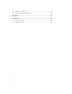
1 1. 1.1 FEATURES Package SIP/SIPMP Camera Cross LAN Cable Software CD Accessory Pack Quick Install Guide Power Lead Cable Package of Products is composed of the main body of the camera, Software CD (NVR Program, Product Manual, NVR Manual), Quick Install Guide, Cross LAN Cable, Accessory Pack, Power Lead Cable. Please check before starting installation.
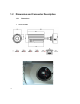
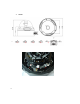
1.2 Dimension and Connector Description 1.2.1 1.
2.
3.
4.
5.
6.
7.
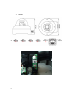
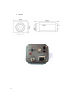
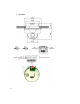
8. SIPMPT ② ⑫ ⑤ ③ ⑨ ⑥ 1.2.2 ① Connector Description 12 Volts DC Power Input Audio Output Audio Input : The SIP Camera supports one audio input and output Video Output : The SIP Camera supports one analog video output with BNC connector.(** Not available on the megapixel series) ⑤ Ethernet Port : Standard RJ45 connector. Supporting POE.
Step 1 : Switch off SIP Camera by disconnecting the power cable. Step 2 : Using a suitable pointed object, press and continue to hold the Reset Button. While continuing to hold the reset button, reconnect the power cable. Step 3 : Keep holding the reset button for 6 seconds, release the reset button. The unit will start up with factory default settings.
2 INSTALLATION 2. 2.1 Minimum System Requirements CPU Pentinum 4 2.
2.2 Preparation before setup To configure your IP device, you have to use Internet Explorer to log in. Before that, your PC’s network settings and the IP device’s IP address must be set up. Make sure all the connections are connected correctly, and then follow the procedures below. 1. Setup your PC network You have to match your PC’s TCP/IP setting with the IP device’s default settings before you can use IE browser to login it. This section tells you how to setup your PC’s TCP/IP settings. 2.
The procedure below is the setup procedure of a PC using Windows XP as its OS. When running an OS other than Windows XP, please refer to the manual included with the OS. 2-13 z STEP 1 Start up your PC.
z STEP 3 Double-click the "Network and Internet connections" icon.
z STEP 5 Click “Local Area Connections”, and then click “Change settings of this connection” in the network Task menu. z STEP 6 Click “Internet Protocol (TCP/IP)”, and then click the [Properties] button.
z STEP 7 Click the “Use the following IP address” radio button and enter the IP address and the subnet mask. Please set the settings as below. IP address: 192.168. 0.xxx Subnet mask: 255.255.255. 0 (NOTE: xxx should be a number from 1 to 254, but 100 is excepted.) z STEP 8 Click the [OK] button and the window dialog box closes.
2.3 Configuring the IP device This section describes how to configure the IP device. The product administrator has unlimited access to all setup windows and normal users can only watch the live image. The IP device is configured under a standard browser (Microsoft Internet Explorer 6.0 or above). Follow the procedures below to configure the IP device. z STEP 1: Open a browser z STEP 2: Enter the IP address of the IP device. The default IP address is “192.168.0.
Once successfully login, the “Video Display page” will be displayed as below.
2.3.1 Video Display This section tells you how to view live images via Internet Explorer. z STEP 1: Click the [Video Display] on the “Main Setup page”. The “Video Display page” is displayed as below. z STEP 2: Check the [MPEG4/MJPEG] to select the Compression type. Once selected, the video server/IP camera will start to stream with new compression type. z STEP 3: Click the [Scale Down] checkbox to scale down the SXGA(1280x1024)/720P(1280x720) to VGA resolution.
z STEP 6: Click the [DO1] Button of trigger / dis-trigger DO function by DO1. z STEP 7: Click the [DO2] Button of trigger / dis-trigger DO function by DO2. z STEP 8: Click the Setup page”. [Quit] to exit the live view and return to “Main NOTE: If the streaming is disabled, you cannot see the live images here. NOTE: Be sure to set the Network Connections Type to Auto Negotiation to respective apparatus connected to this IP device via network.
2.3.2 Host Setting This section tells you how to setup IP device’s host settings and LAN settings. z STEP 1: Click the [Host Setting] on the “Main Setup page”. The “Host setting page” is displayed as below. z STEP 2: Configure these settings with reference to the table below. If you are still unsure what to set, contact your system administrator.
■Network link speed & duplex Parameters WAN port Description This item lets you select the network transmission speed of WAN port. You can select from 1. Auto detect (default setting) 2. 100Mbps / Full duplex 3. 100Mbps / Half duplex 4. 10Mbps / Full duplex 5. 10Mbps / Half duplex ■Port Mapping Parameters TOS (type of service) TOS priority Description Select whether to add the TOS tag onto the streaming data.
2.3.3 WAN Setting This section tells you how to setup IP device’s WAN, DNS server and DDNS server settings. z STEP 1: Click the [WAN Setting] on the “Main Setup page”. The “WAN setting page” is displayed as below z 2-23 STEP 2: Configure these settings with reference to the table below. If you are still unsure what to set, contact your system administrator.
■WAN Setting Parameters Dynamic IP address Description Click this to enable IP device’s DHCP function. It will acquire its WAN port IP address from a DHCP server within the same network. (You must have a DHCP server in order to enable this function.) Click this to manually enter the IP device WAN port IP address. IP address: Enter the WAN port IP address. Static IP Subnet mask: Enter the subnet mask of WAN port. If IP address is changed, adjust the subnet mask accordingly.
z STEP 3: Click the settings or click the [Apply] button of each setting to confirm the [Reset] button to re-enter the parameters. NOTE: Check with your system administrator, if Client PC and IP device are setting in different VLANs, please connect to WAN port. NOTE: Once finished all settings, be sure to click the [Save Reboot] button, otherwise, some settings won’t take effect.
2.3.4 Date Setting This section tells you how to setup IP device’s date and time settings. z STEP 1: Click the [Date Setting] on the “Main Setup page”. The “Date setting page” is displayed as below z STEP 2: Configure these settings with reference to the table below. If you are still unsure what to set, contact your system administrator. ■Date Setting Parameters SNTP/NTP server Description Click this to enable IP device’s SNTP/NTP function.
number in a month; select Type 2 to specify daylight saving time by date. Start Time : Select the daylight savings start time. End Time : Select the daylight savings end time. z STEP 3: Click the [Apply] button of each setting to confirm the settings or click the [Reset] button to re-enter the parameters. NOTE: Once finished all settings, be sure to click the [Save Reboot] button, otherwise, some settings won’t take effect. Manually set date and time will be gone, if power off.
2.3.5 Video Setting This section tells you how to setup IP device’s video and streaming settings. z STEP 1: Click the [Video Setting] on the “Main Setup page”. The “Video setting page” is displayed as below ■Video setting Parameters Camera name Description The camera name is reserved for customer use. Select the streaming mode. 1. TCP only 2. Multicast only Streaming Method 3. RTP Over UDP 4. RTP Over Multicast 5.
RTP B2 Frame Enable Checkbox to enable the B2 frame in RTP streaming Audio Select enable or disable the audio function. Input Sensitivity Select HIGH or LOW of the audio input sensitivity Multicast IP Select the multicast IP. Default settings is 228.5.6.1 Multicast TTL Select the multicast TTL. Default setting is 255. IGMP Select video type connected to the video-in of this IP device. If you use an incorrect video type, some images might be lost.
Only) STEP 3: Click the settings or click the 2-30 [Apply] button of each setting to confirm the [Reset] button to re-enter the parameters.
2.3.6 Video Adjustment This section tells you how to adjust the streaming video. z STEP 1: Click the [Video Adjust] on the “Main Setup page”. The “Video adjust page” is displayed as below 2-31 z STEP 2: Set the checkbox to enable motion detection function. z STEP 3: Set the sensitivity of motion detection windows. z STEP 4: Set the interval time of motion detection. . Within the interval time after the motion event is triggered, no motion event will be triggered.
the motion activity window, you can adjust the motion sensitivity (for more or less activities to be triggered) and the threshold (for how much activity would trigger a motion event. If you are not sure, recommend you to set a. Sensitivity: 80, Threshold: 2~5 (for normal environment) b.
2.3.7 Camera Setup This section tells you how to adjust the camera. z STEP 1: Click the [Camera Setup] on the “Main Setup page”. The “Camera Setup page” is displayed as below ■Camera setting Parameters Description Video Flipping Checkbox to flip the video. Video Mirror Checkbox to mirror the video. Lens Compensation NightTime Gain Threshold Checkbox to load the best video setting for bundled lens. Select the nighttime gain threshold. Select the white balance mode.
1. 3. INDOOR2: Select the indoor white balance profile 2. 4. OUTDOOR1: Select the outdoor white balance profile 1. 5. OUTDOOR2: Select the outdoor white balance profile 2 6. HOLD CURRENT: Select this to let the IP camera automatically obtain a best white balance setting according to current environment. The IP camera will use this setting to adjust color. NOTE: This setting will be lost after you reboot the camera. 7. MANUAL: Select this to enable manual setting of the white balance.
2.3.8 Camera Setup (PTZ camera model) This section tells you how to adjust the camera. z STEP 1: Click the [Camera Setup] on the “Main Setup page”. The “Camera Setup page” is displayed as below ■Camera setting Parameters Description Video Flipping Checkbox to flip the video. Video Mirror Checkbox to mirror the video. BLC Checkbox to enable/disable back light compensation. Select the white balance mode.
Exposure mode AGC Gain Auto IRIS Level Select the Iris level. Sense up Level Select the sense up level. Light Sensor Mode Select light sensor mode. - Auto: The IP camera will auto switch day or night mode. - Day: The IP camera will always day mode. - Night: The IP camera will always night mode. NightTime Gain Threshold Select the nighttime gain threshold. STEP 2: Click the settings or click the 2-36 Select exposure mode. - Auto: The IP camera will adjust the exposure automatically.
2.3.9 PTZ (PT/TZ Camera only) This section tells you how to adjust the camera. z STEP 1: Click the [PTZ] on the “Main Setup page”. The “PTZ page” is displayed as below ■Camera setting Parameters 2-37 Description Pan Speed Select the pan speed. Tilt Speed Select the tilt speed. Home Click the button of go to home function. Reset Click the button of reset the pan/tilt/zoom function. PT Control Click the each button of pan and tilt control.
2-38 Auto Pan Enable Checkbox to enable/disable auto pan function. Entry Select the preset number Dwell Setting the delay time of auto pan function. State Preset state of enable or disable. Add Preset Click the button of add preset number. Del Preset Click the button of del preset number.
2.3.10 User Account Management This section tells you how to setup accounts. z STEP 1: Click the [User account] on the “Main Setup page”. The “Account management page” is displayed as below z STEP 2: Setup the account names and their respective passwords. There are 1 root (administrator) account and 10 common user accounts. Administrator account allows the user to watch the live view and setup everything; but common user account allows user only to watch the live image.
2.3.11 System Info This section tells you how to see the system information of this IP device including system information, WAN status and system log. z STEP 1: Click the [System info] on the “Main Setup page”. The “System information page” is displayed as below z STEP 2: View the information at the 3 columns. This information is very useful to understand the IP device status and to resolve any problem that might occur.
z STEP 3: Click [Parameter List] where you may see all configurations of the IP device. z 2-41 STEP 4: Click [Server Report] to export related information of the IP device while reporting a support to your support channel.
2.3.12 Firmware Upgrade This section tells you how to see update IP device’s firmware. You can always visit our web site for the latest firmware. z STEP 1: Click the [Firmware] on the “Main Setup page”. The “Firmware upgrade page-1” is displayed as below z STEP 2: Click [Apply] button. The ‘’firmware upgrade page-2” will be displayed as below. ■Date Setting Parameters Firmware images file 2-42 Description You can upload the firmware images here.
You can always get the latest version at our website. MD5 file z z You can upload the MD5 file here. Click the [browse] to select an MD5 file and click the [enter]. You can always get the latest version at our website. NOTE: The version of the firmware image and the MD5 file to be uploaded must be the same, otherwise, the firmware upgrading will fail and the IP device will continue using previous firmware version.
2.3.13 Factory Default This section tells you how to see load IP device’s factory default setting. z STEP 1: Click the [Factory Default] on the “Main Setup page”. The “Factory default setting page” is displayed as below 2-44 z STEP 2: Click the [Apply] button to go to loading confirmation page or click the [Reset] button to exit to previous page. z STEP 3: A confirmation page will be displayed. Click the [Save Reboot] button to start loading factory default settings.
2.3.14 Save Reboot This section tells you how to save all the settings and reboot this IP device. This is critical because some settings might not take effect before save and reboot. z STEP 1: Click the [Save and reboot] on the “Main Setup page”. The “Save and reboot page” is displayed as below. z 2-45 STEP 2: The Action LED indicator will light down to indicate that the IP device is rebooting. After around 30 seconds, the Action LED will light up again to indicate that the reboot is completed.
2.3.15 Logout This section tells you how to logout the IP device. Be sure to logout this IP device once your setting is completed. z STEP 1: Click the [Logout] on the “Main Setup page”. You will logout and return to the “Login Page” displayed as below.
2.4 OSD Setting 2.4.
2.4.
2.4.3 z Operating Camera OSD Menu STEP 1: Press the Set button to access the SETUP mode. SETUP menu is displayed on the monitor screen. z STEP 2: Select the desired feature using the UP or DOWN button. Each time you press the UP or DOWN button, the arrow indicator moves up or down. Move the arrow indicator to the desired feature item. z STEP 3: Change the status of the selected feature using the LEFT or RIGHT button. If you press RIGHT or LEFT button, it appears available status.
1. Setting up the LENS Select the lens pressing the RIGHT button. a. On the SETUP menu screen, move the arrow indicator to the lens using the up or Down button. b. Select the desired feature using the LEFT or RIGHT button.
When DC LENS selected, press SET button to control the BRIGHTNESS.
Shutter status and speed control You can control brightness of the screen by the shutter speed. a. Press the SET button to display the setup menu and move the arrow indicator to ‘SHUTTER’ using the UP or DOWN button. b. Set ‘SHUTTER’ the desired mode using the LEFT or RIGHT button.
Manual : When setting shutter speed manually.
ESC : You can control the BRIGHTNESS. c.
2. SLC ( Speco Light Compensation ) – BACKLIGHT A built-in SR chip provides intelligent light level control to overcome serve Backlight conditions. a. Press the SET button to display the SETUP menu and move arrow indicator to ‘BACKLIGHT’ using the UP or DOWN button. b. SET ‘BACKLIGHT’ to the desired mode using the LEFT or RIGHT button.
AUTO GAIN CONTROL (AGC) AGC is to get bright picture. Higher GAIN level, getting brighter screen. However, you can get noise increase. a. Press the SET button to display the SETUP menu and move arrow indicator to ‘AGC’ using the UP or DOWN button. b. SET ‘AGC’ to the desired mode using the LEFT or RIGHT button.
3. WHITE BALANCE (WITE BAL.) For color control on the screen, use ‘WHITE BALANCE’ function. a. Press the SET button to display the SETUP menu and move arrow indicator to ‘WHITE BALANCE’ using the UP or DOWN button. b. SET ‘WHITE BALANCE’ to the desired mode using the LEFT or RIGHT button. ATW (Auto Tracking White Balance) : When color temperature is 2400 ~ 12000K, select this mode. (Ex.
the SET button. Increase or decrease the value for RED(R-Gain) and BLUE(B-Gain), watching the color of the picture, and press the SET button when you obtain the best color. NOTE: Proper White Balance may not be obtained under the following conditions in these cases select the AWC mode. When the scene contains mostly high color temperature object, such as a blue sky or sunset. When the scene is dim. If your camera faces fluorescent lamp directly or is installed in the place of the changing illumination.
4. Digital Noise Reduction (Dynamic Noise Reduction) DNR is to reduce the noise on the screen. a. Press the SET button to display the SETUP menu and move arrow indicator to ‘DNR’ using the UP or DOWN button. b. SET ‘DNR’ to the desired mode using the LEFT or RIGHT button.
5. INTENSIFIER Allows you to get clear images with function under night or low light conditions a. Press the SET button to display the SETUP menu and move arrow indicator to ‘INTENSIFIER’ using the UP or DOWN button. b. SET ‘INTENSIFIER’ to the desired mode using the LEFT or RIGHT button. AUTO : When your camera is under night or low-lighting level, select this mode. NOTE: If you press SETUP at ‘AUTO’ menu from AGC-L to AGC-H sensitivity is increased as well as noise on the screen.
6. NEXT PAGE a. Press the SET button to display the SETUP menu and move arrow indicator to ‘NEXT PAGE’ using the UP or DOWN button. b. SET ‘NEXT PAGE’ to the desired mode using the LEFT or RIGHT button.
CAMERA TITLE a. Press the SET button to display the SETUP menu and move arrow indicator to ‘CAMERA TITLE’ using the UP or DOWN button. b. SET ‘ON’ using the LEFT or RIGHT button. NOTE: If the CAMERA ID feature is set to ‘OFF’, the name will not displayed in the monitor. c. Press the SET button to access tie SETUP mode. d. You cam enter up to 15 characters. ① Move the cursor to character-enter location by using the LEFT or RIGT button. ② Select the desired character by using the UP or DOWN button.
⑤ Select the position at which the CAMERA TITKE will b located on the screen. NOTE: If the CAMERA feature is set to ‘OFF’, the name will not displayed in the monitor. After erasing the character from right to left, correct the character again.
7. CAMERA TITLE You can choose color and B/W mode electronically. (OPTION) ON : Color mode OFF : B/W mode AUTO : generally color mode, B/W mode in low luminance. NOTE: OSD Key may not work for 3 seconds when the color B/W mode is changed.
8. SYNC Two SYNCHRONIZATION modes are available… INTERNAL and EXTERNAL LINE-LOCK. In LINE_LOCK mode, the camera sync to the 60HZ phase. a. Press the SET button to display the SETUP menu and move arrow indicator to ‘SYNC’ using the UP or DOWN button. b. SET to the desired mode using the LEFT or RIGHT button. INT : Internal synchronization L/L : if you choose ‘L/L’, you can adjust the desired phase. - Press the SET button. - You can adjust the desired phase from 0 to 270.
9. PRIVACY To mask an area that you want to be private. a. Press the SET button to display the SETUP menu and move arrow indicator to ‘PRIVACY’ using the UP or DOWN button. b. SET ‘PRIVACY’ to the desired mode using the LEFT or RIGHT button. OFF : Deactivation ON : PRIVACY mode activated - Press the SET button. - Move the arrow indicator to area you want to mask. - Set ‘ON’ using LEFT or RIGHT button. - Press the SET button and then set the area’ bounds with the method like MOTIN DET.
10. REVERSE a. Press the SET button to display the SETUP menu and move arrow indicator to ‘REVERSE’ using the UP or DOWN button. b. SET ‘REVERSE’ to the desired mode using the LEFT or RIGHT button. OFF : Deactivation ON : Make a reverse turn to RIGHT or LEFT.
11. DETAIL a. Press the SET button to display the SETUP menu and move arrow indicator to ‘DETAIL’ using the UP or DOWN button. b. SET ‘DETAIL’ to the desired mode using the LEFT or RIGHT button.
ON : DETAIL control mode (level 0~31) When the level is up, the sharpness will increase. Control this level to get your best picture quality. If the level is too high, you can get an unnatural image with video noise. 12. DEFAULT Use to reset your camera to FACTORY DEFAULT SETTING. 13.
2.4.
A. Dome Setup To enter Dome setup, use the five keys right to move when cursor on dome setup. DOME SET CAMERA ID : CAM1□□□□□□□□□□□□ RECOVER : OFF MANUAL SPEED : 100°/S AUTO FLIP : OFF ZOOM SPEED : FAST ALARM : DISABLE LANGUAGE : ENGLISH [NEXT PAGE] SAVE AND EXIT EXIT DEFAULT SETTING A-1. DOME SET - CAMERA ID To set camera ID, select up to 16 characters using five keys to the left or right.
“right or left” to select ON or OFF. The default setting is OFF. A-5. DOME SET – ZOOM SPEED Zoom speeds are selectable FAST or SLOW mode. the right direction for selecting FAST or SLOW. FAST. A-6. Move five keys to The default setting is DOME SET – ALARM All alarms are available after set as ENABLE Mode. Move five keys to right or left direction for selecting ENABLE/DISABLE. The default setting is DISABLE. A-7.
The default setting is BLANK. ENTER PASSWORD BY ENTERING PRESET CODE PASSWORD *** CONFIRM *** Press any number from 001~255 with preset button on password blank and again it on confirm blank. Then “CONFIRMED” is displayed on the monitor and the menu will go back to the previous page automatically.
OSD DISPLAY CAMERA ID : OFF PRESET ID : OFF SECTOR ID : OFF COORDINATE: ON [PREVIOUS PAGE] A-8-4. DEFAULT SETTING DOME SET – [NEXT PAGE] – [SYSTEM STATUS] This page shows the information of this camera. SYSTEM STATUS PROTOCOL : PELCO D, P BAUD RATE : 2400 BPS FIRMWARE VER. : 2.00 UPGRADED DATE : 06.
INITIALIZATION [TOUR CLEAR] [PRESET CLEAR] [SECTOR CLEAR] [PRIVACY CLEAR] [PATTERN CLEAR] [LOAD OPTIMIZED DEFAULT] [PREVIOUS PAGE] - To clear memorize any data, move five keys to the right direction when cursor is on each item. TOUR CLEAR TOUR CLEAR ARE YOU SURE? YES NO Press FOCUS NEAR button when the cursor is at YES in order to clear memorized data. Then flickered each item such as tour, preset, sector and so on is displayed on the monitor about 2~3 seconds.
A-9. DOME SET – [NEXT PAGE] – SAVE AND EXIT To saving the memorized data and escape this page, move five keys to the right direction when cursor is at SAVE AND EXIT. A-10. DOME SET – [NEXT PAGE] – EXIT In order not to save any data and wants to escape this page, move five keys to the right direction when cursor is at EXIT B.
sharpens the edges in the picture. The default seeting is 10. (the aperture level is from 01 ~ 15) (10X Zoom) B-4. CAMERA SET – D ZOOM Move five keys to the right direction in order to set as ON, if Digital Zoom is necessary at install field. The default setting is OFF. (10X Zoom) B-5. CAMERA SET – WB MODE White balance functions have 4 modes according to the condition of exterior lighting. The default setting is AWB and it may change the mode option accoding to the lighting conditions as below.
If DSS turns on, digital slow shutter is working. Per second, the electronic shutter will remain open to receive some more lighting. (10X Zoom) B-10. CAMERA SET – EXIT To escape this page, move five keys to the right direction. C. PRESET SET To enter PRESET SET, move five keys to the right direction. PRESET SET PRESET NO :001 PRESET ID :PRESET001------PAN :XXX.XX TILT : XXX.XX SAVE EXIT C-1. DEFAULT SETTING PRESET – PRESET NO. Up to 165 numbers of preset positions are available.
press FOCUS FAR button again after setting a preset location. C-4. PRESET – SAVE Move five keys to the right direction when the cursor is at SAVE and then the cursor will be located on Preset ID for the continuous preset No. setting. C-5. PRESET – EXIT To escape this page, move five keys to the right direction. D. AUTO SCAN SET AUTO SCAN SET START ANGLE : XXX.X.XX.X END ANGLE : XXX.X.XX.X DIRECTION : CW ENDLES : OFF SPEED : 10°/S DWELL TIME: 03 SAVE AND EXIT EXIT D-1.
CW: Clock wise direction (Default) CCW: Count Clock Wise Direction. D-4. AUTO SCAN – ENDLESS Auto Scan can use endless rotation, move five keys to the right direction in order to select ON. Otherwise, the default setting is OFF. D-5. AUTO SCAN – SPEED User can use auto scan speed from 05°/S up to 35°/S and the default setting is 10°/S D-6. AUTO SCAN – DWELL TIME To select dwell time, move five keys to the left or right direction in order to adjust dwell time.
E. TOUR SET 8 Programmable tours can be set and each tour is available to set up to 64 preset steps. TOUR SET TOUR NO : 01 TOUR TITLE : TOUR01□□□□□□□□□□ TOUR STEP : 01 PRESET NO. : 01 DWELL TIME : 03 SPEED : 200°/S SAVE EXIT DEFAULT SETTING E-1. TOUR SET – TOUR NO. Max. 8 group tour no. set by the five keys are available. E-2. TOUR SET – TOUR TITLE To set tour title, select up to 16 characters using Five keys to left or right.
setting is 03 seconds. E-6. TOUR SET – SPEED Each tour step can be set with different tour speed up to 200°/S and it is selectable from 10°/S. Move five keys to the right or left direction to select tour speed. The default setting is 200°/S. E-7. TOUR SET – SAVE To save the memorized data and escape this page, move five keys to the right direction when cursor is at SAVE E-8. TOUR SET – EXIT To escape this page, move five keys to the right direction F.
F-3. PRIVACY SET – ACTION(MOVE/ADJUST) To set the blocking area, press FOCUS FAR button when the MOVE MODE is appeared. Then use the five keys to the user defined area in order to set blocking area. Then press FOCUS FAR button again to escape from MOVE MODE. To adjust size of blocking area, move five keys to the right or left direction when the cursor is on ACTION. After move mode changed to ADJUST MODE, press FOCUS FAR button in order to adjust the size of blocking area.
G-1. PATTERN SET – PATT NO. Up to 8 programmable user-defined patterns set by the five keys on the Webviewer GUI are available. G-2. PATTERN SET – PATT TITLE To set PATTERN TITLE, select up to 16 characters using Five keys to the left or right.
H. ALARM SET 4 Alarm inputs are available and each alarm is activating to presets, group tours or patterns. ALARM SET ALARM NO : 01 ALARM INPUT: OFF ALARM ACT : 001 SAVE EXIT H-1. DEFAULT SETTING ALARAM SET – ALARM NO. Up to 4 alarms are selectable by using five keys to the right direction when cursor is on ALARM NO. H-2. ALARAM SET – ALARM INPUT Input alarm ways provide two different ways as NC (Normal Close) or NO (Normal Close) The default setting is OFF H-3.
I. SECTOR SET Up to 8 programmable sectors are available with 16 characters. This feature is useful to memory the certain location such as parking zone or so on. When camera goes through this area, it shows the letter you memorized. SECTOR SET SECTOR SECTOR SECTOR SECTOR SAVE EXIT Start Position NO : 01 ID : SECTOR01□□□□□□□□ START: XXX.X.XX.X END : XXX.X.XX.X End Position DEFAULT SETTING I-1. SECTOR SET – SECTOR NO. Up to 8 programmable sectors set by the five keys are available. I-2.
I-5. SECTOR SET – SAVE After setting the SECTOR position, to save the data, move five keys to the right direction when the cursor is on SAVE. After saving the data, the cursor moves to SECTOR NO.2 automatically to prepare the next SECTOR. I-6. SECTOR SET – EXIT To escape this page, move five keys to the right direction J. EXIT To escape OSD Main Menu, move five keys to the right or left direction then this camera is ready to operate.
2.4.5 DIP SW SETTING (SIPSD10X only) Mini Speed Dome camera provides up to 63 camera ID and it’s adjustable ID with 1st~6th of Dip switch Open the camera case, set ID using DIP SW1. * Factory default: Camera ID = 1, PELCO-D Termination Baud rate Protocol ID Set 2.4.
010100XXXX 10 000001XXXX 32 011011XXXX 54 110100XXXX 11 100001XXXX 33 111011XXXX 55 001100XXXX 12 010001XXXX 34 000111XXXX 56 101100XXXX 13 110001XXXX 35 100111XXXX 57 011100XXXX 14 001001XXXX 36 010111XXXX 58 111100XXXX 15 101001XXXX 37 110111XXXX 59 000010XXXX 16 011001XXXX 38 001111XXXX 60 100010XXXX 17 111001XXXX 39 101111XXXX 61 010010XXXX 18 000101XXXX 40 011111XXXX 62 110010XXXX 19 100101XXXX 41 111111XXXX 63 001010XXXX 20 010101XXXX 42
3 APPENDIX 3. 3.1 Specification 3.1.1 SIP Camera Series * Network Spec.
* Camera Spec. SIPB1 Image Sensor Horizontal Resolution Total Pixels Effective Pixels Color Motion Detection Privacy 1/3" Sony Super HAD CCD 410K 540 TV Lines 811 x 508(NTSC) 768 x 494 (NTSC) 1/60 ~ 1/200,000sec (NTSC) 1/50 ~ 1/200,000sec (PAL) 0.002Lux (Intensifier), 0.3Lux (Shutter) DC Auto Iris Vari-Focal Lens f=2.8~11mm 1 : 1.3 ~ 2.
SIPB2 Image Sensor Horizontal Resolution Total Pixels Effective Pixels Color Motion Detection Privacy 1/3" Sony Super HAD CCD 410K 540 TV Lines 811 x 508(NTSC) 768 x 494 (NTSC) 1/60 ~ 1/200,000sec (NTSC) 1/50 ~ 1/200,000sec (PAL) 0.002Lux (Intensifier), 0.3Lux (Shutter) DC Auto Iris Vari-Focal Lens f=5~50mm 1 : 1.3 ~ 2.
SIPD3 Image Sensor Horizontal Resolution Total Pixels Effective Pixels Color Motion Detection Privacy 1/3" Sony Super HAD CCD 410K 540 TV Lines 811 x 508(NTSC) 768 x 494 (NTSC) 1/60 ~ 1/200,000sec (NTSC) 1/50 ~ 1/200,000sec (PAL) 0.002Lux (Intensifier), 0.3Lux (Shutter) DC Auto Iris Vari-Focal Lens f=2.8~11mm 1 : 1.3 ~ 2.
SIPD4 Image Sensor Horizontal Resolution Total Pixels Effective Pixels Color Motion Detection Privacy 1/3" Sony Super HAD CCD 410K 540 TV Lines 811 x 508(NTSC) 768 x 494 (NTSC) 1/60 ~ 1/200,000sec (NTSC) 1/50 ~ 1/200,000sec (PAL) 0.002Lux (Intensifier), 0.3Lux (Shutter) DC Auto Iris Vari-Focal Lens f=5~50mm 1 : 1.3 ~ 2.
SIPT5 Image Sensor Horizontal Resolution Total Pixels Effective Pixels Color Motion Detection Privacy 1/3" Sony Super HAD CCD 410K 540 TV Lines 811 x 508(NTSC) 768 x 494 (NTSC) 1/60 ~ 1/200,000sec (NTSC) 1/50 ~ 1/200,000sec (PAL) 0.002Lux (Intensifier), 0.3Lux (Shutter) C/CS Mount Lens selectable 1 : 1.3 ~ 2.
SIPSD10X Pan Rotation Angle Day & Night (ICR) Digital Slow Shutter S/N Ratio BLC OSD (On Screen Display) White Balance Flickerless AGC Motion Detection 360˚ Endless Manual 10˚ ~ 200˚/sec Preset Max 200˚ /sec 0˚ ~ 90˚ Manual 10˚ ~ 200˚/sec Preset Max 200˚ /sec 0.02˚ 164 positions with a 16-character label available for each position with different speed steps Max.
Dimensions(HxD) 167 ø x 167 mm Weight 1.6kg 3.1.2 SIPMP Camera Series * Network Spec.
* Camera Spec. SIPMPB Image Sensor Effective Pixels Electric Shutter Lens Min. scene Illumination Synchronization S/N Ratio Flickerless Day/Night White Balance AGC BLC Motion Detection Power Source 1/3" Micron Progressive Scan CCD 1280 x 1024 1/10 ~ 1/2,000sec (60Hz) 1/10 ~ 1/2,000sec (50Hz) F 4.3mm, f1.8 / 75Deg(Horizontal) 0.5 Lux at F1.
SIPMPD Image Sensor Effective Pixels Electric Shutter Lens Min. scene Illumination Synchronization S/N Ratio Flickerless Day/Night White Balance AGC BLC Motion Detection Power Source 1/3" Micron Progressive Scan CCD 1280 x 1024 1/10 ~ 1/2,000sec (60Hz) 1/10 ~ 1/2,000sec (50Hz) F 4.3mm, f1.8 / 75Deg(Horizontal) 0.5 Lux at F1.
SIPMPT5 Image Sensor Effective Pixels Electric Shutter Lens Min. scene Illumination Synchronization S/N Ratio Flickerless Day/Night White Balance AGC BLC Motion Detection Power Source 1/3" Micron Progressive Scan CCD 1280 x 1024 1/10 ~ 1/2,000sec (60Hz) 1/10 ~ 1/2,000sec (50Hz) F 4.3mm, f1.8 / 75Deg(Horizontal) 0.5 Lux at F1.