SIPSD37X & HTSD37X 37X Optical Indoor / Outdoor Speed Dome Cameras 200 New Hightway Amityville, NY 11701 631-957-8700 www.specotech.com Speco Technologies is constantly developing product improvements. We reserve the right to modify product design and specifications without notice and without incurring any obligation. Rev. 03082010.
CAUTION RISK OF ELECTRIC SHOCK DO NOT OPEN CAUTION: TO REDUCE THE RISK OF ELECTRICAL SHOCK, DO NOT OPEN THE COVERS. NO USER SERVICEABLE PARTS INSIDE. REFER SERVICING TO QUALIFIED SERVICE PERSONAL This lightning flash with arrowhead symbol is intended to alert the user to the presence of un-insulated "dangerous voltage" within the product's enclosure that may be of sufficient magnitude to constitute a risk of electric shock to persons.
NOTICE Important Safety Guide 1. Read and follow all the Instructions Read all the safety and operating instructions before using the product. 2. Keep this manual Keep this manual for reference in future. 3. Attachments / Accessories Use only the attachments or accessories specified by the manufacturer. 4. Installation z Do not install near any heat sources such as radiators, heat registers, stoves, or other appratus including amplifiers that product heat.
NOTICE Caution Operating z Before using, make sure that the power supply is properly installed. z While operating, if any abnormal condition or malfunction is observed, stop using the product immediately and then contact your local dealer. Handling z Do not disassemble or tamper with the parts inside the product. z Do not drop or subject the product to shock and vibration as this can damage the product. z Care must be taken when you clean the clear dome cover.
TABLE OF CONTENTS ① Introduction Features Package Components Main Part Description ② Installation DIP Switch Setup Installation with Wall Mount Bracket Wiring and Cabling ③ Operation Check Points before Operation Check Points for Preset and Pattern Function before Operation OSD Menu Reserved Preset (Hot Keys) Preset Swing Pattern Group Other Functions OSD Display ④ OSD Menu Quick Programming Guide Main Menu Display Setup Privacy Zone Mask Setup Camera Setup Motion Setup Preset Setup Swing Setup Pattern Setu
INTRODUCTION 1 Features Powerful Zoom Camera & Setup Options z Image Sensor: Sony 1/4" Double density interline transfer CCD z Zoom: 37X Optical Zoom, 12X Digital Zoom z Day & Night, Privacy Mask and WDR z SNR (Super Noise Reduction) Function z Various Focus Modes: Auto-Focus, Manual Focus, Semi-Auto Focus z Various Setup Options in OSD Menu. Powerful Pan/Tilt Functions z MAX.
INTRODUCTION 1 z MAX. 8 sets of Swing are programmable. This function is that the camera moves repetitively between two preset positions at programmed speeds. z MAX. 4 Patterns are programmable. This function is that the camera memorizes the path (mostly curve path) by the joystick of the controller and revives the trajectory operated by the joystick as closely as possible. z MAX. 8 sets of Group are programmable.
INTRODUCTION 1 Network Function(Only for the SIPSD37X) z Network functions including remote monitoring, bidirectional audio and others are available through IP based network such as LAN, ADSL/VDSL, and Wireless LAN. For more information, refer to the separated manual for IP Addressable models. Perfect Outdoor Environment Compatibility and Easy Installation z The fans and heaters are built-in in the camera for cold and hot temperature environment.
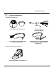
INTRODUCTION 1 Package Component Product & Accessories z Main Body & Surface Mount Bracket z Accessories for The Models with Alarm In/Out Function [I/O Cable] z Default Accessories [Main Cable,Wrench] z Accessories for The IP Addressable Models [Crossover LAN Cable,Audio Cable,CD] SIPSD37X Only Wall Mount Brackets (Included) [Screws :Machine M5×15,Hex Lag #14×50] 37X Speed Dome Camera 9/50
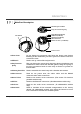
INTRODUCTION 1 Main Part Description Mounting Screw Hole Drop Prevention Spring DIP Switch Reset Switch (IP Model) LAN Port (IP Model) Audio Port (IP Model) Main Connector Sensor I/O Port (I/O Model) Dome Cover z Dome Cover Do not detach the protection vinyl from the dome cover before finishing all the installation process to protect the dome cover from scratches or dust. z DIP Switch Used to set up camera IDs and protocols.
INSTALLATION 2 DIP Switch Setup Before installing the camera, set up the DIP switch to configure the camera ID and the communication protocol. Camera ID Setup z ID numbers of cameras are set up with binary numbers. See the examples shown below. ON ON 1 2 3 4 5 6 7 8 Pin 1 2 3 4 5 6 7 8 BinaryValue 1 2 4 8 16 32 64 128 on off off on on off off on off off off off off off off off ex) ID=5 ex) ID=10 z The camera ID range is “1~255”.
INSTALLATION 2 Communication Protocol Setup z Select an appropriate Protocol with the DIP switch combination. ON ON 1 Switch Mode 2 3 4 P0 (Pin 1) P1 (Pin 2) P2 (Pin 3) Protocol OFF OFF OFF PELCO-D, 2400 bps ON OFF OFF PELCO-D, 9600 bps OFF ON OFF PELCO-P, 4800 bps ON ON OFF PELCO-P, 9600 bps Others Reserved z Match the camera protocol with the camera protocol in the setting of your DVR or controller to control the camera. z Adjust the DIP switch after turning off the camera.
INSTALLATION 2 Terminal Resistor Setup The terminal resistor is used for the following cases. ON ON 1 2 3 4 z Case 1 : In case that the control cable length between a camera and a controller is relatively very long (1:1 Connection) If the communication cable length is very long, the electrical signal will bound in the terminal point. This reflected signal causes distortion of original signal. Accordingly, the camera can be out of control. In this case, the terminal resistor of both sides i.e.
INSTALLATION 2 Installation with Wall Mount Bracket ① Make a hole whose diameter is 30~40mm ② Hook up “Drop Prevention Spring” on main body to prevent camera from on the mounting surface to pass the unexpected drop and pull the wire(s) and wire(s) and cable(s) through the mounting cable(s) for the system as below. surface. (In case of the wiring and cabling through the mounting surface only) Then prepare the wall mount bracket. Pull the wire(s) and cable(s) for the system as below.
INSTALLATION 2 Wiring and Cabling POWER INTERNET BROWSER LAN CABLE MIC SPEAKER AUDIO CABLE MAIN CABLE BNC MONITOR RS-485 I/O CABLE CONTROLLER / DVR SENSOR I/O IR SENSOR Port Description z Main Cable Port Pin Number (RJ45) 1 2,4 5 3 7 6,8 z I/O Cable Port Pin Number (RJ25) 1 2 3 4 5 6 37X Speed Dome Camera Connector / Wire Color DOOR SWITCH Red Yellow Orange White Signal Video + Video − RS-485 + RS-485 − Power + Power − Wire Color Blue Yellow Green Red Black White Signal IN COM + IN 1 −
INSTALLATION 2 Power Description z Carefully check the voltage and current capacity of the rated power. The rated power is indicated in the back of main unit. 24VAC is used on the HTSD37X (AC 17V~29V, 1.5A) 12VDC is used on the SIPSD37X (DC11V~18V, 3.0A) z For the DC input models, be careful with the polarity of DC power. The system should be permanentally damaged by wrong DC input. z In case that the length of the power wire is very long, there may be voltage drop and the syatem may not work properly.
INSTALLATION 2 Video z Use BNC coaxial cable only. Alarm Input Internal +5V~12V IN COM+ + - IN 1- Sensor 1 + - IN 3- Sensor 3 + - Before connecting sensors, check driving voltages and output signal types of the sensors. Since output signal types of the sensors are divided into Open Collector type and Voltage Output type in general, the wiring must be done properly after considering those types. Signal Description IN COM+ The electric power source to drive input circuit.
OPERATION 3 Check Points before Operation z Before turning on the system, check if the wire(s) and cable(s) are connected properly. z Check if the camera ID on the controller is properly selected. The camera ID must be identical to that of the target camera. The camera ID can be checked by reading the DIP switch of the camera or on OSD. z If your controller supports multi-protocols, the protocol must be changed to match to that of the camera. z Adjust the DIP switch after turning off the camera.
OPERATION 3 OSD Menu z Function With OSD menu, the system can be properly configured for each application. z Entering into OSD Go Preset [95] Reserved Presets (Hot Keys) z Description Some Preset numbers are reserved to change some parameters without entering into OSD menu.
OPERATION 3 Preset z Function MAX. 127 positions are programmable. The Preset number can be assigned from 1 to 128 except 95. Preset 95 is reserved for entering into OSD menu. Camera parameters such as White Balance, Auto Exposure and others can be set up independently and each preset can have its own parameter values independently from the other persets. When setting up presets with a controller, Label should be blank and "Camera Adjust" should be set to "GLOBAL" as the default.
OPERATION 3 Pattern z Function This function is that the camera memorizes the path (mostly curve path) by the joystick of the controller and revives the trajectory operated by joystick as closely as possible. MAX. 4 Patterns are programmable and Maximum 1200 communication commands can be programmed in a pattern. z Setting Patterns A Pattern can be created by the following methods. Method 1) [Pattern NO.] { The Pattern programming window appears on the monitor as below.
OPERATION 3 Group z Function This function is that the camera memorizes the combination of Presets, Pattern and/or Swings sequently and runs Presets, Pattern and/or Swings repetitively. MAX. 8 sets of Group are programmable. Each group can have MAX. 20 actions which are the combination of Preset, Pattern and Swing. Preset speed can be set up and the repeat number of Pattern & Swing can be set up in Group setup. Dwell time between actions can be set up also.
OPERATION 3 z Alarm Input 3 Alarm Inputs are available. When external sensors activate, the camera runs pre-defined actions such as Preset, Pattern, Swing and Group. After the pre-defined time period passed, “Post Alarm” activates, which is pre-defined. Note that only the latest alarm input is effective when multiple sensors are activated at the same time. z Privacy Zone Mask Privacy Zone Mask allows the user to program 8(or 4) rectangulars that can not be viewed by the operator of the system.
OPERATION 3 OSD Display Preset Label Camera ID LABEL12345 CAM 1 PRESET1 I:-2- O:1 15/4/x1/N Action Title Alarm Information P/T/Z Information z P/T/Z Information Displays the amount of pan from zero degree vertical, the amount of tilt from zero degree horizontal and current compass direction. Also identifies the amount of the zoom magnification. z Camera ID Displays the selected Camera ID (Address). z Action Title Identfies Actions "SET PRESET xxx" When Preset xxx is memorized.
OSD MENU 4 Quick Programming Guide The menu items with < > always have sub-menus. To go to submenus or make the cursor move to the right, press NEAR key. To go to the previous-upper level menus, press FAR key. To make a selection, press NEAR key To cancel a selection, press FAR key To move the cursor in the menu, use the joystick to the Up/Down direction or Left/Right direction. z To change a value of an item, use Up/Down of the joystick in the controller. z To save changes, press NEAR key.
OSD MENU 4 Display Setup DISPLAY SETUP -----------------------CAMERA ID ON PTZ INFORMATION AUTO ACTION TITLE AUTO PRESET LABEL AUTO ALARM I/O AUTO BACK EXIT Display setup allows you to program how labels are displayed on the monitor. In case of AUTO, the labels are displayed on the monitor when there are any changes in parameters. z Camera ID [ON/OFF] Displays the (Address).
OSD MENU 4 Compass Direction Setup SET NORTH DIRECTION ------------------------ Move the camera to a target position and press NEAR button to save the direction as North. The direction is the reference direction to assign other compass directions.
OSD MENU 4 Privacy Zone Mask Area Setup EDIT MASK 1 ------------------------ Move your camera to an area to mask. Then a mask and the menu to adjust the mask size will be displayed. MOVE TO TARGET POSITION [NEAR:SELECT/FAR:CANCEL] Privacy Zone Mask Size Setup EDIT MASK 1 ------------------------ [ [ Adjusts the mask size. Use the joystick or the arrow buttons of your controller to adjust mask size. z (Left/Right) Adjusts the mask width. z (Up/Down) Adjusts the mask height.
OSD MENU 4 Camera Setup ZOOM CAMERA SETUP -----------------------FOCUS MODE SEMIAUTO DIGITAL ZOOM ON IMAGE FLIP OFF SHARPNESS 16 STABILIZATION OFF Sets the general functions of zoom camera module. z Focus Mode BACK EXIT [AUTO/MANUAL/SEMIAUTO] Sets camera Focus mode. { SEMIAUTO Mode This mode automatically exchanges focus modes between Manual Focus mode and Auto Focus mode by operation.
OSD MENU 4 z Stabilization [ON/OFF] Compensates image vibrations by wind or others. The images with vibrations are compensated by Digital Zoom function and the image resolution with this function should be lower than normal image resolution when this function is turned on. Also this function may not work properly in the following cases.
OSD MENU 4 Auto Exposure Setup AE SETUP - GLOBAL -----------------------BACKLIGHT OFF DAY/NIGHT AUTO BRIGHTNESS 50 IRIS AUTO SHUTTER ESC AGC MIDDLE SSNR MIDDLE SENS-UP BACK EXIT 37X Speed Dome Camera z Backlight [OFF/WDR/BLC/HLC] or [OFF/BLC/HLC] or [ON/OFF] Sets Backlight Compensation. If a bright backlight is present, the subjects in the picture may appear dark or as a silhouette. Backlight compensation enhances objects in the center of the picture.
OSD MENU 4 37X Speed Dome Camera z IRIS [AUTO/MANUAL(F1.6~F28)] or [AUTO/MANUAL(0~100)] Sets Iris to operate automatically or at a userdefined level. If Iris is set to Auto, Iris has higher priority in adjusting AE and Shutter Speed is fixed. Auto iris is the lens function that automatically opens closes the iris in response to changing light conditions. If Iris is set to Manual, Iris is fixed and Iris has lower priority in adjusting AE, in comparison with others. z Shutter Speed [ESC/A.
OSD MENU 4 WDR (Wide Dynamic Range) Setup WDR -----------------------LIMIT MIDDLE LEVEL 50 z Limit [LOW/MIDDLE/HIGH] z Level [0~100] BACK EXIT HLC (High Light Compensation) Setup HLC -----------------------LIMIT LOW COLOR 5 BACK EXIT 37X Speed Dome Camera z Limit [AUTO/MANUAL] When there are too bright lights, this function blocks light sources on images to have better images.
OSD MENU 4 Motion Setup MOTION SETUP -----------------------MOTION LOCK OFF PWR UP ACTION ON AUTO FLIP ON JOG MAX SPEED 120/SEC JOG DIRECTION INVERSE FRZ IN PRESET OFF BACK EXIT 37X Speed Dome Camera Sets the general functions of Pan/Tilt motions. z Motion Lock [ON/OFF] If Motion Lock is set to ON, it is impossible to set up and delete Preset, Swing, Pattern and Group. It is possible only to run those functions.
OSD MENU 4 Parking Action Setup PARKING ACTION SETUP -----------------------PARK ENABLE OFF WAIT TIME 00:10:00 PARK ACTION HOME BACK EXIT 37X Speed Dome Camera This feature allows the camera to begin a specified action after a programmed time of inactivity. z Park Enable [ON/OFF] If Park Enable is set to ON, the camera runs an assigned function automatically if there is no PTZ command during the programmed "Wait Time". z Wait Time [1~59 sec. / 1~180 min.
OSD MENU 4 Alarm Input Setup ALARM INPUT SETUP -----------------------ALARM NO. 1 TYPE ACTION HOLD TIME POST ACTION N.OPEN NOT USED ENDLESS HOME BACK EXIT Defines Alarm Function. When an alarm is receive, an input signal to the camera triggers the user-defined action programmed for the alarm. z Alarm No [1~3] Selects a sensor number to set up. z Type [Normal OPEN/Normal CLOSE] Selects sensor operation type.
OSD MENU 4 Preset Setup PRESET SETUP -----------------------PRESET NO. 1 CLR PRESET RELAY OUT CAM ADJUST z Preset Number [1~128] Selects a preset number to set up. If a selected preset is already defined, the camera moves to the pre-defined position and preset parameters such as Label and CAM Adjust show on the monitor. If a selected preset is not defined, “UNDEFINED” shows on the monitor. z Clear Preset [CANCEL/OK] Deletes the data of the selected Preset.
OSD MENU 4 Preset Scene Setup EDIT SCENE - PRESET 1 ------------------------ 1 Use the Joystick to move the camera to a desired ○ position. 2 Save the preset position by pressing NEAR key. ○ 3 Press FAR key to cancel targeting the preset position. ○ MOVE TO TARGET POSITION [NEAR:SAVE /FAR:CANCEL] Preset Label Setup EDIT LABEL - PRESET 1 -----------------------[ ] ---------1234567890 OK ABCDEFGHIJ CANCEL KLMNOPQRST UVWXYZabcd efghijklmn opqrstuvwx yz<>-/:.
OSD MENU 4 Swing Setup SWING SETUP -----------------------SWING NO. 1 1ST POS. NOT USED 2ND POS. NOT USED SWING SPEED CLEAR SWING RUN SWING 30/SEC CANCEL z Swing Number [1~8] Selects a Swing number to edit. If the selected Swing is not defined, "NOT USED" is displayed in the 1st Position and the 2nd Position. z 1st Position 2nd Position [PRESET 1~128] Sets the 2 positions for a Swing function. If the selected preset is not defined, "UNDEFINED" is displayed as shown below.
OSD MENU 4 Pattern Setup PATTERN SETUP -----------------------PATTERN NO. 1 UNDEFINED CLR PATTERN CANCEL RUN PATTERN BACK EXIT z Pattern Number [1~4 ] Selects a Pattern number to edit. If the selected pattern number is not defined, "UNDEFINED" will be displayed under the selected pattern number. z Clear Pattern [CANCEL/OK] Deletes the data of the selected pattern. z Run Pattern Runs the Pattern for the test purposes to check if it works properly.
OSD MENU 4 Group Setup GROUP SETUP -----------------------GROUP NO. 1 UNDEFINED CLEAR GROUP CANCEL RUN GROUP BACK EXIT z Group Number [1~8] Selects a Group number to edit. If the selected Group number is not defined, "UNDEFINED" will be displayed under the selected Group number. z Clear Group [CANCEL/OK] Deletes the data of the selected Group. z Run Group Runs the Group for the test purposes to check if it works properly. z Edit Group Edit the selected Group.
OSD MENU 4 EDIT GROUP 1 -----------------------NO ACTION ### DWELL OPT -----------------------1 NONE 2 NONE 3 NONE 4 NONE 5 NONE -----------------------SAVE [ :MOVE CURSOR] CANCEL [ :CHANGE VAL.] EDIT GROUP 1 -----------------------NO ACTION ### DWELL OPT -----------------------1 PRESET 1 00:03 360 2 NONE 3 NONE 4 NONE 5 NONE -----------------------SAVE [ :MOVE CURSOR] CANCEL [ :CHANGE VAL.
OSD MENU 4 EDIT GROUP 1 -----------------------NO ACTION ### DWELL OPT -----------------------1 PRESET 1 00:03 360 2 NONE 3 NONE 4 NONE 5 NONE -----------------------SAVE CANCEL 37X Speed Dome Camera ⑥ After finishing setting up, press FAR key to exit. Then the cursor will move to “SAVE”. Press Near key to save the data.
OSD MENU 4 System Initialization SYSTEM INITIALIZE -----------------------CLEAR ALL DATA NO CLR DISPLAY SET NO CLR CAMERA SET NO CLR MOTION SET NO CLR EDIT DATA NO REBOOT CAMERA NO REBOOT SYSTEM NO BACK EXIT z Clear All Data Deletes all configuration data and the system is set to the factory default. z Clear Display Set Initializes all the configuration data for Display. z Clear Camera Set Initializes all the configuration data for Camera.
SPECIFICATIONS 5 Specifications HTSD37X / SIPSD37X Video Signal Format Image Sensor Total Pixels Effective Pixels Horizontal Resolution Video Signal-to-Noise Zoom Forcal Length Angle ofView Zoom Speed Minimum Illuminance Day & Night Focus Iris Shutter Speed AGC White Balance BLC Flickerless SSNR Privacy Zone Stabilization 37X Speed Dome Camera NTSC Sony 1/4'' Double Density Interline Transfer CCD 811(H)×508(V) 410K 768(H)×494(V) 380K 550 TV Lines(Color), 680 TV Lines(B/W) 50 dB (AGC Off) 37X Optical Zoom,
SPECIFICATIONS 5 MECHANISM PART Movement Range Speed Pan Tilt Preset Jog Swing Preset Pattern Swing Group Other Pan/Tilt Functions Communication Protocol OSD Sensor Input Alarm Outputs Fan Heater Operating Temperature 37X Speed Dome Camera 360°(Endless) 90° 360°/sec. 0.05 ~ 360°/sec. (Proportional to Zoom) 1~ 180°/sec. 127 Presets (Label, Independent Camera Parameter Setting) 4 Patterns [1200 Commands(Approx. 5 Minute) / Pattern] 8 Swings 8 Groups (MAX.
SPECIFICATIONS 5 MECHANICAL Ceiling Mount Material EBO/EBI model Dome Internal External Dome Size Dimension Weight Wall Mount Polycarbonate Polycarbonate,ABS Aluminium ∅150mm / ∅ 5.9” ∅192×265.3 mm Approx 3.2 Kg 296×276.6 mm Approx 3.8 Kg [Note] 1) Specification and features are subject to change without prior notice. 2) Check the voltage and current capacity of rated power carefully.
SPECIFICATIONS 5 Dimension z Main Body 144 155 5 7. 10 z Wall Mount Type 118.6 80 277.9 100 229.8 138.
WARRANTY 6 37X Speed Dome Camera 49/50
200 New Hightway Amityville, NY 11701 631-957-8700 www.specotech.com Rev.03082010 Speco Technologies is constantly developing product improvements. We reserve the right to modify product design and specifications without notice and without incurring any obligation. 37X Speed Dome Camera Rev.