User Manual M185LCBV4 and M215LCBV4 LCD VIDEO MONITOR
SAFETY INSTRUCTIONS…………………………………………………………………….2-3 CAUTION ………………………………………..……………………………………………..4 FCC RF INTERFERENCE STATEMENT …………………………………………………...5 CONNECTING WITH EXTERNAL EQUIPMENT………………………………………….. 6 CONTROLS AND FUNCTIONS…………………………………………………….……......7-16 MOUNTING GUIDE …………………………………………………………….……..…….. 17 D-SUB CONNECTOR PIN ASSIGNMENTS ……………………………………………….18 POWER MANAGEMENT……………………………………………………………………..19 SPECIFICATIONS………………………………………………………………………..……20 .
1. Read all of these instructions. 2. Save these instructions for later use. 3. Follow all warnings and instructions in this manual and on the product. 4. Unplug this product from the wall outlet before cleaning. Do not use liquid or aerosol cleaners. Use a damp cloth for cleaning. 5. Do not use this product near water. 6. Do not place this product on an unstable cart, stand, or table. The product may fall, causing serious damage to the product or nearby people. 7.
14. Unplug this product from the wall outlet and refer servicing to qualified service personnel under the following conditions: A. When the power cord or plug is damaged or frayed. B. If liquid has been spilled into the product. C. If the product has been exposed to rain or water. D. If the product does not operate normally when the operating instructions are followed.
▶ NEVER REMOVE THE BACK COVER Removal of the back cover should be carried out only by qualified personnel. ▶ DO NOT USE IN HOSTILE ENVIRONMENTS To prevent electrical shock or a fire hazard, do not expose the unit to rain or moisture. This unit is designed to be used in the office or home. Do not subject the unit to vibrations, dust, or corrosive gases. ▶ KEEP IN A WELL VENTILATED PLACE Ventilation holes are provided on the cabinet to prevent the temperature from rising.
NOTE This equipment has been tested and found to comply with the limits for a Class B digital device, pursuant to Part 15 of the FCC Rules. These limits are designed to provide reasonable protection against harmful interference in a residential installation. This equipment generates, uses, and can radiate radio frequency energy and, if not installed and used in accordance with the instructions, may cause harmful interference to radio communications.
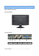
Bottom and Side Panel Control Back View of Monitor A. Connector Panel 1 1. Audio In 2 3 2. Audio Out 5 4 3. BNC Out 4. BNC In 5.
B. CONTROL KEYS/BUTTONS Buttons are located on the back of the monitor on the right side of the Bezel. 1. Menu/Source: Opens the OSD and steps down on the OSD. Also, the MENU button selects either the VGA or BNC input after the EXIT button is pushed) and then press the MENU button to Select 2. Up: Increases the volume or moves the selector/indicator right in the OSD 3. Down: Decreases the volume or moves selector/indicator left in the OSD 4.
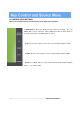
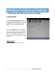
1. OSD setup under BNC input mode A. COLOR MENU Press the MENU button to bring the menu on screen, and then Up/ Down buttons to move left and right across the menu selections to highlight the COLOR menu. Press the Menu (Source) button to enter the (highlighted) COLOR sub menu. Each additional press of the Menu/Source button moves the yellow highlighted sub-menu selection downward, moving from the bottom selection back to the top of the sub-menu.
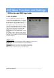
1. OSD setup under BNC input mode (continued) B. AUDIO MENU Press the MENU button to bring the menu on screen, and then Up / Down buttons to move left and right across the menu selections to highlight the AUDIO menu. Press the Menu (Source) button to enter the (highlighted) AUDIO sub menu. Pressing the Up/ Down buttons will adjust the value of the highlighted item. Press the MENU button to save the values. Press EXIT to exit the sub-menu and go back to the main menu choices.
1. OSD setup under BNC input mode (continued) C. OSD MENU Press the MENU button to bring the menu on screen, and then Up / Down buttons to move left and right across the menu selections to highlight the OSD menu. Press the Menu (Source) button to enter the (highlighted) OSD sub menu. 4 : Each additional press of the Menu/Source button 3 moves the yellow highlighted sub-menu selection downward, moving from the bottom selection back to the top of the sub-menu.
1. OSD setup under BNC input mode (continued) D. MISC Press the MENU button to bring the menu on screen, and then Up / Down buttons to move 4left :and right across the menu selections to highlight 3 the MISC menu. Press the Menu (Source) button to enter the (highlighted) MISC sub menu. Each additional press of the Menu/Source button moves the yellow highlighted sub-menu selection downward, moving from the bottom selection back to the top of the sub-menu.
2. OSD setup under VGA input mode A. COLOR MENU Press the MENU button to bring the menu on screen, and then Up / Down buttons to move left and right across the menu selections to highlight the COLOR menu. Press the Menu (Source) button to enter the (highlighted) COLOR sub menu. Each additional press of the Menu/Source button moves the yellow highlighted sub-menu selection downward, moving from the bottom selection back to the top of the sub-menu.
2. OSD setup under VGA input mode (continued) B: IMAGE MENU Press the MENU button to bring the menu on screen, and then Up / Down buttons to move left and right across the menu selections to highlight the IMAGE menu. Press the Menu (Source) button to enter the (highlighted) IMAGE sub menu. Each additional press of the Menu/Source button moves the yellow highlighted sub-menu selection downward, moving from the bottom selection back to the top of the sub-menu.
2. OSD setup under VGA input mode (continued) C. AUDIO MENU Press the MENU button to bring the menu on screen, and then Up / Down buttons to left 4 move : and right across the menu selections to 3 highlight the AUDIO menu. Press the Menu (Source) button to enter the (highlighted) AUDIO sub menu. Each additional press of the Menu/Source button moves the yellow highlighted sub-menu selection downward, moving from the bottom selection back to the top of the sub-menu.
2. OSD setup under VGA input mode (continued) D. OSD MENU Press the MENU button to bring the menu on screen, and then Up / Down buttons to move left and right across the menu selections to highlight the OSD menu. Press the Menu (Source) button to enter the (highlighted) OSD sub menu. Each additional press of the Menu/Source button moves the yellow highlighted sub-menu selection downward, moving from the bottom selection back to the top of the sub-menu.
2. OSD setup under VGA input mode (continued) E. MISC Press the MENU button to bring the menu on screen, and then Up / Down buttons to move left and right across the menu selections to highlight the MISC menu. Press the Menu (Source) button to enter the (highlighted) MISC sub menu. Each additional press of the Menu/Source button moves the yellow highlighted sub-menu selection downward, moving from the bottom selection back to the top of the sub-menu.
Wall or Other Mounting with VESA Standard CAUTION: The wall mount must bear a minimum of five times the monitor’s net weight. To mount your MONITOR to the wall or another surface, you need to purchase a VESA wall mount. Use four M4 x 8mm screws (not included) to attach the mount. The monitor mount VESA hole pattern is 100mm x 100mm. Note: Metric (M4 x 8 mm) is the type screw that should be used (do not use longer screws or the monitor may be damaged). Screws 1.
▶ PIN ASSIGNMENTS ▶ ACCESSORIES 1. Quick Installation 2. Power Cord 3. VGA Cable Guide 4.
POWER CONSUMPTION :<20W LED INDICATOR The power management feature of the monitor is comprised of three stages: On (Green Light), No Signal (Flashing Green Light), and Off (No Light).
Model Size Aspect Ratio Resolution (H x V) M185LCBV4 M215LCBV4 18.5” LCD CCTV monitor 21.5” LCD CCTV monitor 16:9 1360 x 768 1920 x 1080 Colors 16.