HT7248FFi 540 Line Color Dome Camera Intensifier Series, Focus Free Wall & Ceiling Mountable Please read this manual thoroughly before operation and keep it handy for further reference.
WARNING & CAUTION CAUTION RISK OF ELECTRIC SHOCK DO NOT OPEN CAUTION : TO REDUCE THE RISK OF ELECTRIC SHOCK DO NOT REMOVE COVER (OR BACK). NO US E R S E R V I C E A B L E P A RT S I N SIDE REFER SERVICINGTO QUALIFIED SER V ICE PERSONNEL.
Contents Package Contents 3 Precautions 4 Camera Installation 5~8 Features 9~10 OSD Setting 11~16 Troubleshooting 17~18 Specification 19 Dimensions 20 Warranty 21 2
PACKAGE CONTENTS • Please make sure that the following items are included in the package: 1 HT7248FFi Camera 2 Mounting Screws 1 Chameleon Dome Cover 1 Video Test Cable Please leave this manual with the end-user for future reference.
PRECAUTIONS • THIS DOME CAMERA SHOULD BE ONLY INSTALLED BY QUALIFIED PERSONNEL • TO PREVENT A FIRE OR ELECTRICAL HAZARD PLEASE USE PROPER POWER CABLE. THE DOME COVER SHOULD BE TREATED WITH CARE • DO NOT CELAN THE COVER WITH AN ABRAISIVE CLEANING MATERIAL - PLEASE USE A SOFT CLOTH OR TISSUE TO CLEAN THE DOME COVER • THERE ARE NO USER-SERVICEABLE PARTS INSIDE.
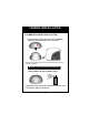
CAMERA INSTALLATION 1. CONNECT POWER CABLE 1) WHEN USING 12 VOLTS DC (constant voltage 600 mA) -CONNECT ACCESSORY CABLE TO THE CABLE LEAD OF THE CAMERA AND CONNECT 12V DC POWER SUPPLY. POWER INPUT:RED CONNECT CENTER:(+) POWER SUPPLY 2) WHEN USING 24 VOLTS AC (40 Volt Amps) CAMERA RED(+) CONNECT AC 24V BLACK:(-) POWER SUPPLY 3) CONNECT VIDEO CABLE -CONNECT BNC CABLE TO THE BNC JACK. YELLOW:VIDEO OUT 4) CONNECT RS-485 CABLE -CONNECT 2WIRE CABLE TO THE 485PORT AS BELOW.
CAMERA INSTALLATION 2. CHAMELEON COVER INSTALLATION 1) If you wish to change the color of the HT-7248FFi, place the Chameleon Dome over the camera Place the Chameleon Dome over the HT-7248FFi and push until it snaps into position.
CAMERA INSTALLATION 3. CONTROL BOARD 1 2 3 4 1) Video Test Terminal For second video output 2) OSD (On Screen Display) Joy stick Press the Joy stick for one second until the OSD menu tree appears on the screen. Move the Joy Stick up, down, left & right to control the OSD functions. 3) DIP Switch setting for RS485 Please see the next page for controlling this switch.
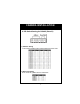
CAMERA INSTALLATION 4. DIP Switch Setting for RS-485 (Pelco-D) 1 2 3 4 5 6 1) Address Setting to set Camera Address, place switches based on below chart. 2) Baud rate Setting to set Baud rate, please refer the chart below.
Features SLC When the image is in front of strong background lighting, your camera allows you to get a clear image. INTENSIFIER 1/3 inch density CCD and digital processor permit high quality pictures to be captured in very low light condition. High Resolution Horizontal resolution of 540 TV lines is achieved by using a SONY Double Speed CCD with 410,000 pixels, yielding pictures with a high S/N ratio..
OSD All camera functions are menu driven for easy use. Dynamic Noise Reduction The Intensifier camera has a DSP chip that can remove image noise efficiently showing clean images in low light conditions. ELECTRONIC DAY/NIGHT The Intensifier camera can show color pictures in all lighting conditions, or you can have it automatically switch to a B/W picture in low light conditions MANUAL / AUTO IRIS LENS The Intensifier camera will work with auto iris, manual iris and fixed iris lenses.
Operating your camera OSD Function SETUP MENU LENS TYPE ● DC IRIS SHUTTER TYFE ● ELC ● FIXED WHITE BALANCE ● ATE ● AWC SLC ● HIGH ● MANUAL ● MANUAL ● MIDDLE ● LOW ● OFF AUTO GAIN ● HIGH ● MIDDEL ● LOW ● OFF REDUCE NOISE ● HIGH ● MIDDLE ● LOW ● OFF INTENSI FIER ● AUTO ● OFF NEXT PAGE ● CAMERA TITLE ● DAY/NIGHT ● SYNC ● MOTION ● PRIVACY ● REVERSE ● DETAIL ● DEFAULT ● PAGE1 EXIT 11
SETUP Menu Functions 1. LENS (DC) – Lens is static with DC auto iris lens only 2. SHUTTER (Option : OFF / FLK / MANUAL/ ESC) Flickerless mode (FLK) reduces on-screen flickering. Electronic Shutter Control (ESC) adjusts brightness level on screen. Manual mode allows you to adjust the shutter speed from 1/60~1/120,000 of a second (NTSC). 3. WHITE BAL. (Option : ATW / MANUAL / AWC) Select Auto Tracking White Balance (ATW) when the color temp. is 2400°K~12000°K.
5. Auto Gain ( Low / Middle / High) Increase the GAIN level to brighten the picture. (noise / distortion may develop) 6. REDUCE NOISE (Low / Middle / High) Reduces noise/distortion on the screen, Increasing the REDUCE NOISE level reduces noise but may introduce video Artifacts, it is deactivated if AGC is turned off. 7. INTENSIFIER Automatically provides a clear image under low-light conditions.
NEXT PAGE Menu Functions 1. CAMERA ID UP, DOWN, LEFT, RIGHT menu control = Select a character, then press (SETUP)MENU to accept it. The character is saved and the title cursor at the bottom of the screen moves to the next position. ← → = Go back or forward in the title name to make changes. CLR = Delete the entire name and start again. POS = Position the camera title on the screen. Press (SETUP)MENU to confirm the position. END = Accept the new name. 2.
3. SYNC (INT / Line Lock) INT : When line lock is not required. It synchronize the vertical interval sync pulse of your camera with other equipment to reduce the effect of picture roll on the monitor. L/L : Adjust the vertical phase (VPH) from 000 ~ 359 Line Lock is only available with 24VAC power. 4. MOTION Detects moving objects on screen and displays MOTION DETECTED along with the number of movements counted. Allows you to select the area on screen you want to observe.
5. PRIVACY Allows you to mask certain areas of the screen from observation AREA SEL = Select a motion detection grid (top left, top right, bottom left, bottom right) to modify. AREA STATE = Activate or deactivate the selected grid. TOP/DOWN/ = Press LEFT or RIGHT menu control left or LEFT/RIGHT right to alter the dimensions of the selected grid. 6. MIRROR Produces a horizontal mirror image on screen. 7. SHARPNESS Sharpens the image on screen.
Troubleshooting If you have trouble operating your camera, refer to the following Problem Nothing appears on the screen. Solution ● Check that the power cord and line connection between the camera and monitor are proper ● Check that you have properly connected VIDEO cable the camera VIDEO output jack. The image on the screen is dim. The image on the screen is dark. ● Is lens stained with dirt? Clean your lens with soft, clean cloth. ● Set the monitor to proper condition.
Solution Problem The color of the picture is not matched. ● Check that you have properly set the ‘ WHITE BALANCE ’ menu The image on the screen flickers. ● Is the camera facing to direct sunlight or fluorescent lighting? Change the camera position. L/L mode isn’t able to be selected. ● Have you connected your camera to DC power source? Connect it to AC power source.
SPECIFICATIONS ITEM HT – 7248FFi Power Source 12VDC & 24VAC ( Dual Voltage ) Power Consumption 500mA (DC) / 6.6W (AC) Image Sensor 1/3”, SONY SUPER HAD CCD, Total Pixels 811(H) x 508(V) , 1/3” CCD Effective Pixels 768(H) x 494(V) , 1/3” CCD LENS TYPE Focus Free Lens 3.5~10mm Maximum Aperture Ratio 1 : 1.3 ~2.0 Scanning System 2 : 1 Interlaced 525 Lines / 60 Fields / 30 Frames Synchronization Internal / Line Lock selectable Video Output 1.
DIMENSIONS * SIDE VIEW * TOP VIEW 20
WARRANTY 21
MEMO
200 New Highway Amityville, NY 11701 631-957-8700 www.specotech.com VER. 080901 This manual is based on the date as shown in the right and specifications are subject to Change without notice for quality improvement.