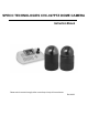
SPECO TECHNOLOGIES CVC-927PTZ DOME CAMERA Instruction Manual Please read this manual thoroughly before use and keep it handy for future reference. Rev.
Warnings and Cautions WARNING TO REDUCE THE RISK OF FIRE OR ELECTRIC SHOCK, DO NOT EXPOSE THIS PRODUCT TO RAIN OR MOISTURE. DO NOT INSERT ANY METALLIC OBJECTS THROUGH THE VENTILATION GRILLS OR OTHER OPENINGS ON THE EQUIPMENT.
FCC COMPLIANCE STATEMENT FCC INFORMATION: THIS EQUIPMENT HAS BEEN TESTED AND FOUND TO COMPLY WITH THE LIMITS FOR A CLASS A DIGITAL DEVICE, PURSUANT TO PART 15 OF THE FCC RULES. THESE LIMITS ARE DESIGNED TO PROVIDE REASONABLE PROTECTION AGAINST HARMFUL INTERFERENCE WHEN THE EQUIPMENT IS OPERATED IN A COMMERCIAL ENVIRONMENT.
IMPORTANT SAFEGUARDS 1. 2. 3. 4. 5. 6. 7. Read these instructions. Keep these instructions. Heed all warnings. Follow all instructions. Do not use this apparatus near water. Clean only with dry cloth. Do not block any ventilation openings. Install in accordance with the manufacturer's instructions. 8. Do not install near any heat sources such as radiators, heat registers, stoves, or other apparatus (including amplifiers) that product heat. 9.
Table of Contents Chapter 1 — Introduction ..............................................................1 1.1 Features..............................................................................................1 Chapter 2 — Installation and Configuration ..................................3 2.1 Package Contents ..............................................................................3 2.2 Basic Configuration Of Fastrax II E Dome Camera System ...............4 2.3 Setting Dome Camera Termination.....
3.7 Tour ..................................................................................................15 3.8 Pattern ..............................................................................................17 3.9 Alarm.................................................................................................18 3.10 Area Title.........................................................................................18 3.11 Privacy Zone ...........................................................
Dome Reset ........................................................................................................... 30 System Information ................................................................................................ 30 Appendix A — Specifications.......................................................31 Appendix B — Troubleshooting...................................................34 Appendix C — Glossary ..............................................................
Chapter 1 — Introduction 1.1 Features The Fastrax II E dome camera and the Fastrax II Keyboard Controller make up the building blocks for any surveillance/security system. Using multiple Keyboard Controllers and multiple dome cameras, no place is too large for monitoring. Extensible and flexible architecture facilitates remote control functions for a variety of external switching devices such as multiplexers and DVRs.
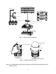
UP TO 255 MULTIPLEXER Alarm Input UP TO 8 UP TO 99 DVR Alarm Output UP TO 4 UP TO 32 CAMERA J-box Master Keyboard Figure 1 – Typical System Configuration push bubble ring ass'y remove camera window screw push remove window assemble bubble ring ass'y Figure 2 – Assemble bubble ring ass’y Note : It is recommended to remove camera window for improving picture quality when you use bubble ring ass’y.
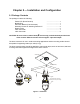
Chapter 2 — Installation and Configuration 2.1 Package Contents The package contains the following. Fastrax II E (Dome Camera) Bubble Ring Instruction Manual (This Document) Assembly Screws for Attaching Fastrax II E Plastic Anchor 10Pin Connector 12Pin Connector ………………………1 ………………………1 ………………………1 ………………………3 ………………………3 ………………………1 ………………………2 CAUTION: Be sure to have caution labels(E version only) on both the body and the base of the camera. Different version will not support input and output.
2.2 Basic Configuration of Fastrax II E Dome Camera System.
The dome camera must be installed by qualified service personnel in accordance with all local and federal electrical and building codes. The system should be installed according to Figures 4 through 9. Termination Switches SW1 ON KSD02H 9A 1 2 on 1 2 3 4 1 2 3 4 4 56 4 56 4 56 1 on 8 78 S4 23 4 56 on 8 1 1 23 23 4 56 23 78 9 01 23 4 56 78 S5 9 01 78 9 01 S1 S6 9 01 78 9 01 S2 9 01 78 S3 8 Address(ID) and Protocol selection Switches 23 Figure 5– Layout of Switches 2.
Figure 7- Termination Diagram 6
2.4 Setting Dome Camera Address (ID) To prevent damage, each dome camera must have a unique address (ID). When installing multiple dome cameras using a multiplexer, it is suggested that the dome camera address match the multiplexer port number. If you want to set the address more than 999, you should contact the service provider. Example: Port 1 = Dome 1, Port 2 = Dome 2 … Port 16 = Dome 16.
2.5 Setting Dome Camera Protocol If a dome camera is to be installed with a Fastrax keyboard controller, select F2 protocol. Consult service personnel if a dome camera is installed with device other than a keyboard controller.
2.6 Connections • Connecting to the RS485/ 422 The dome camera can be controlled remotely by an external device or control system, such as a control keyboard, using RS485 half-duplex , RS422 duplex or simplex serial communications signals. Connect Marked Rx+, Rx- to Tx+ and Tx- of the RS485 control system. If control system is RS422, connect Rx+(Tx+), Rx+(Tx-) and Rx+, Rx- of the dome camera to Tx+, Tx- and Rx+, Rx- of the control device respectively.
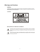
RAM TEST CHECK NO. : OK! CHECK AAAA : OK! CHECK 5555 : OK! FASTRAX II E Vx.xxx CAMERA TYPE xxxx WAIT DOME SETTING. INIT TILT ORGIN SET OK INIT PAN ORGIN SET OK INIT CAMERA SET OK PRESET No. CAMERA TITLE 001 PRESET PRESET TITLE or AREA TITLE CAMERA ID INFORMATION DISPLAY FUNCTION UNDER RUNNING EMPTY DATA ! T001 ALARM:1 DOMEID:0001 W→360.0,090.
Chapter 3 — Program and Operation 3.1 Dome Camera Selection Before you program or operate a dome camera, you must select the dome camera by pressing the dome camera No. + CAM Example: Pressing 1 , 0 and CAM key sequentially will select dome camera 10. The selected dome camera ID will be displayed on the LCD monitor of the keyboard controller. 3.
3.3 How to control the On-Screen Menu Utility Action Function Call the On-screen menu utility MENU Joystick left or right Go into the sub-menu items. Execute the command(exit) Change value. Navigate through the menu items. Joystick up or down Navigate through the menu items. Finish editing title. Joystick down Zoom handle twist Change value. Enter editing title mode. CTRL + Joystick Change value of angle Escape (EXIT) ESC 3.
1. Press the SCAN key to enter Auto Scan menu directly. Or press the MENU key to display the main menu on the monitor. Scroll to Auto Scan and push the Joystick to the right. 2. Select an Auto Scan number by pushing the Joystick left or right. 3. Twist the Joystick to enter the title by scrolling through the alphanumeric characters and pushing the handle to the right or left to move to the next space. Press ENTR key or push the Joystick down to finish title mode. 4.
3.5 Preset (Second Item of the Main menu / Shortcut: PRST ) If you need to view specific places routinely, you should program presets. A preset is a programmed video scene with automatic pan, tilt, zoom, focus and iris settings. Once programmed, entering the number and pressing a Preset button on your controller automatically calls up the preset. In addition, presets may be assigned to alarm actions or as the “home” position for the dome camera.
5. After aiming the camera (view direction and lens control), release CTRL/PGM . Then twist the Joystick handle or Press Tele or Wide Key to store the selected view. The position number will be displayed and the user will be prompted to enter a preset title. 6. Enter the title for the preset position using the Joystick . (Rotate handle clockwise and counterclockwise or press Tele or Wide Key to scroll through the alphanumeric characters, push the handle to right or left to select next or previous digit.) 7.
Tour2 executes as follows: Preset3 Î Preset4 Î Preset7 Î Preset5 Î Preset1 … Repeat (Tour4 is still valid if called directly from Tour2.) TOUR 01:xxxxxxxxxxxxxxxx SCAN TYPE:NORMAL === === 003 === === === === A08 === === === === === === === T02 === 001 === === === === === === T08 === === === === === === === === === === === === === === === === === SAVE AND EXIT(ESC TO CANCEL) PRESS FUNCTION KEY AND ROTATE JOYSTICK TO SELECT NUMBER.
through the alphanumeric characters. Push the handle to the right or left to select the next or previous digit. 9. Select Save and Exit by pushing the Joystick to the right. Press ESC to exit the program without saving. NOTE: Press the Home key at a programmed position to delete programmed function. In the Tour mode, in conjunction with preset and Auto Scan, you can make the camera travel from a preset position to another preset position at a specific speed.
7. Pressing ESC will not save your information and exits to the previous mode. Press the HOME key at any programmed position to delete that programmed pattern. NOTE: If total recording time reaches 240 seconds, it will automatically stop for a moment and restart recording. Previous data will be overwritten. 3.
3.10 Area Title (Sixth Item of Main menu) Enter a specific name on programmed angle between START and END. For the screen below, when the camera points at an angle between 124.3° to 359.5°, ABC will be displayed on the screen. AREA TITLE SETUP NO TITLE START END 01 ABC 124.3 359.
3.11 Privacy Zone (Seventh Item of Main menu) Hide up to 8 unwanted views in a camera. PRIVACY ZONE SETUP NO TITLE METHOD 01 xxxxxxxxxxxxxxxx ON BLOCK 02 xxxxxxxxxxxxxxxx OFF V.OFF 03 xxxxxxxxxxxxxxxx NONE ==== 04 xxxxxxxxxxxxxxxx NONE ==== 05 xxxxxxxxxxxxxxxx NONE ==== 06 xxxxxxxxxxxxxxxx NONE ==== 07 xxxxxxxxxxxxxxxx NONE ==== 08 xxxxxxxxxxxxxxxx NONE ==== SAVE AND EXIT(ESC TO CANCEL) 1. Press MENU to display the main menu on the monitor.
3.12 Camera (Eighth Item of Main menu) – HID2404SxExxx MODEL NOTE: The menu features will vary depending on the camera module installed in your dome camera.
• WB (white balance) CONTROL WB SETUP MODE : AUTO R GAIN : 210 B GAIN : 155 EXIT(ESC TO EXIT) MODE MANUAL / AUTO / INDOOR / OUTDOOR / ONE PUSH / ATW RGAIN 0 ~ 255 BGAIN 0 ~ 255 Use the ATW mode for normal use. RGAIN / BGAIN modes are controllable only in MANUAL Mode Push the Joystick to the right or left to change. NOTE : “ONE PUSH” means that when rotating the Joystick handle for a moment the lens moves to adjust the focus for the subject.
• LINE LOCK CONTROL LINE LOCK SETUP MODE : INTERNAL PHASE : 125 EXIT(ESC TO EXIT) MODE INTERNAL / EXTERNAL PHASE 0~255 EXIT (ESC TO EXIT) Adjusts phase of picture with other cameras in EXTERNAL mode. • NIGHT SHOT MENU The NIGHT SHOT option removes the IR cutoff filter of the camera and makes the camera sensitive to near infrared. The picture will appear greenish. This may be suppressed by setting the BLACK & WHITE option to ON. The operator can enable NIGHT SHOT for all dome cameras at the same time.
3.13 Camera (Eighth Item of Main menu) – HID2404HCExxx MODEL NOTE: The menu features will vary depending on the camera module installed in your dome camera. CAMERA SETUP FOCUS CONTROL WB CONTROL AE CONTROL LINE LOCK CONTROL SHARPNESS : 32 BACK LIGHT : OFF DIGITAL ZOOM : OFF (2X,4X,MAX) NIGHT SHOT CONTROL SAVE AND EXIT(ESC TO CANCEL) SHARPNESS The higher the value, the more edges in the picture will be enhanced (0~63). BACK LIGHT Objects in front of bright backgrounds will be clearer with BLC ON.
• WB (white balance) CONTROL WB SETUP MODE : AUTO R GAIN : 133 B GAIN : 133 EXIT(ESC TO EXIT) MODE MANUAL / AUTO RGAIN 0 ~ 255 BGAIN 0 ~ 255 Use the AUTO mode for normal use. RGAIN / BGAIN modes are controllable only in MANUAL Mode Push the Joystick to the right or left to change. • AE CONTROL AE SETUP MODE : AE (DSS) SLOW SHUTTER : 1/4 IRIS : F2.
• LINE LOCK CONTROL LINE LOCK SETUP MODE : INTERNAL PHASE : 125 EXIT(ESC TO EXIT) MODE INTERNAL / EXTERNAL PHASE 0~255 EXIT (ESC TO EXIT) Adjusts phase of picture with other cameras in EXTERNAL mode. • NIGHT SHOT MENU The NIGHT SHOT option removes the IR cutoff filter of the camera and makes the camera sensitive to near infrared. The picture will appear greenish. This may be suppressed by setting the BLACK & WHITE option to ON. The operator can enable NIGHT SHOT for all dome cameras at the same time.
3.14 Dome Setup (Ninth Item of Main menu) CONFIGURATION MENU HOME FUNCTION SETUP OSD DISPLAY VIEW ANGLE SETUP INITIALIZE DATA ORIGIN OFFSET DOME RESET SYSTEM INFORMATION EXIT(ESC TO EXIT) • HOME FUNCTION SETUP After a dome control menu item has been selected, follow the directions below to set the function.
• OSD DISPLAY DISPLAY SETUP CAMERA TITLE : DOMEID VIEW DIRECTION : OFF DOME OSD DISPLAY : ON AREA DISPLAY : OFF SAVE AND EXIT(ESC TO CANCEL) CAMERA TITLE VIEW DIRECTION DOME OSD DISPLAY AREA DISPLAY : 8 CHARACTER CAN BE SET : ON / OFF : ON / OFF : ON / OFF • VIEW DIRECTION “ON” sets current direction as N(north) and the coordinate angle to 000. “OFF” hides the directional title. Every 90 degrees of clockwise rotation will change the title to E(East), S(South), W(West).
• PANNING RANGE When the dome camera is installed near a wall, panning range can be limited by user. PANNING RANGE SETUP RIGHT LIMIT : 000.0 LEFT LIMIT : 000.0 ENABLE : OFF SWAP RIGHT/LEFT SAVE AND EXIT(ESC TO CANCEL) • FLIP Allows the dome camera to automatically turn 180 degrees when the camera tilts to its lower position. When the camera reaches the floor directly above the moving object, it will stop. Release the Joystick handle instantly and then pull down to run the flip function.
Erase all stored data from the Flash-ROM of the selected dome camera. You will be asked to enter Yes or No. If you intend to erase all data then press the MENU key, otherwise press the ESC key to exit without erasing. The erased data includes all stored data (titles, presets, and tours….) except origin offset. The offset value is still valid after all data is erased. The offset value can be zeroed only with default set of Offset origin menu.
Appendix A — Specifications Camera(HID2404SLExxx) Image Sensor 1/4" Super HAD Color CCD (Sony) Picture elements NTSC : 768x494 Approx. 380K pixels PAL : 752x582 Approx. 440K pixels Horizontal Resolution 470 / 460 lines(NTSC/PAL) Lens 18x optical zoom with auto focus 12x digital zoom F1.4 to F3.0, f=4.1mm to 73.8mm View angle Approx. 48° (WIDE end) to 2.7° (TELE end) Minimum Illumination S/N ratio 1.0 Lux(F1.
View angle Approx. 45° (WIDE end) to 2° (TELE end) Minimum Illumination 2.5 lux(F1.4,normal shutter speed) 0.2 lux (F1.4,1/4S(NTSC) OR 1/3S(PAL) 0.01 lux (1/4s with IR Cut Filter Removed) S/N ratio more than 49Db Image stabilizer ON/OFF Camera(HID2404HCExxx) Image Sensor 1/4" Progressive scan CCD Picture elements NTSC : 758x504 Approx. 380K pixels PAL : 758x592 Approx. 450K pixels Horizontal Resolution 470 / 470 lines(NTSC/PAL) Lens 23x optical zoom with auto focus 10x digital zoom F1.
General Certification Electrical Input Voltage CE EMC, FCC CLASS A, UL 18 to 30 VAC; 24 VAC nominal, built-in power-line surge Power Requirement 24 VAC/VDC 850mA Power Consumption Maximum 20W Alarm Output Alarm Input Control Access Time ID (Camera Address) Mechanical Dimension Weight Pan Angle Speed 4 Normal relays 24 VDC/1A Max (selectable NC/NO) 8 Normal dry contact (selectable NC/NO) RS-485/422 baud rate: 2400 ~230k bps (default:9600bps) 0.
Appendix B — Troubleshooting If problems occur, verify the installation of the camera with the instructions in this manual and with other operating equipment. Isolate the problem to the specific piece of equipment in the system and refer to the equipment manual for further information. Problem Possible Solution No video. Verify that power is connected to all pieces of equipment in the system. Verify that the power switches are in the ON position. Check the video connections (see Figure 4).
Appendix C — Glossary Alarm Actions The assigned responses for the dome camera when inputs change from normal to abnormal states. The dome may run a Preset, Pattern, or have no assigned action for each of the four dome inputs. The dome may also send alarm states to the host controller for processing. See also Input and Normal Input State. Areas Programmed start and end points of the dome's field of view around its pan axis. Each area is a part of a circular viewing area that extends around the dome.
IR Mode A feature of the camera that permits manual or automatic switching between color and IR (black-and-white) operation. When IR mode is active, clearer images may be obtained under low-light conditions. Line Lock Allows you to phase lock the video with the AC power line. When line lock is enabled, it prevents vertical video rolling when switching multiple cameras to a single monitor. If text appears slightly tinted on color monitors, disabling the line lock may prevent this problem.
Privacy Zones Masked areas of the dome camera's viewing area. These masks prevent operators of the surveillance system from viewing these designated zones. The Privacy Zones move in relation to the dome camera’s pan/tilt position. In addition, the apparent size of the Privacy Zone adjusts automatically as the lens zooms in or out. Up to eight Privacy Zones may be established for a dome camera. Shutter Limit Setting used to define the maximum exposure time for the Open Shutter setting.
Appendix D — Short Cut Key Short Cut Key PRST TOUR PTRN SCAN NO.+ PGM + PRST NO.+ PGM + TOUR NO.+ PGM + SCAN 1 ~ 4 + ON 1 ~ 4 + OFF 10 + ON 10 + OFF 11 + ON 11 + OFF 12 + ON 12 + OFF 13 + ON 13 + OFF 14 + ON 14 + OFF 15 + ON 15 + OFF 100 + ON 101 + ON 102 + ON 103 + ON 104 + ON 104 + OFF 105 + ON 105 + OFF 150 + ON 150 + OFF Function Pop up preset setup menu. Pop up guard Tour setup menu. Pop up Pattern setup menu. Pop up Auto Scan setup menu. Store the current view at the selected number.
SPECODOME CAMERA 040705 39