CVC-6246iHR 540 Line Color Dome Camera Intensifier Series Wall & Ceiling Mountable Please read this manual thoroughly before operation and keep it handy for further reference.
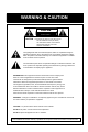
WARNING & CAUTION CAUTION RISK OF ELECTRIC SHOCK DO NOT OPEN CAUTION : TO REDUCE THE RISK OF ELECTRIC SHOCK DO NOT REMOVE COVER (OR BACK). NO USER SERVICEABLE PARTS INSIDE REFER SERVICINGTO QUALIFIED SERVICE PERSONNEL.
Contents Package Contents 3 Precautions 4 Camera Installation 5 Internal Components 7 Features 9 1
Operating Your Camera 11 SET UP 13 SET UP LENS 14 SHUTTER SPEED CONTROL 15 BACK LIGHT 19 AUTO GAIN (AGC) 20 WHITE BALANCE 21 REDUCE NOISE 23 INTENSIFIER CAMERA TITLE 24 25 DAY/NIGHT/SYNC 27 MOTION DETECTION 29 PRIVACY 31 REVERSE 32 DETAIL 33 DEFAULT/RETURN 34 Troubleshooting 35 Specifications / Dimensions 37 Warranty 39 2
PACKAGE CONTENTS • Please make sure that the following items are included in the package: 1 CVC-6246iHR Camera 2 Mounting Screws 1 Video test Connector 1 Power Adaptor Lead Please leave this manual with the end-user for future reference.
PRECAUTIONS • THIS DOME CAMERA SHOULD BE ONLY INSTALLED BY QUALIFIED PERSONNEL • TO PREVENT A FIRE OR ELECTRICAL HAZARD PLEASE USE PROPER POWER CABLE • THE DOME COVER SHOULD BE TREATED WITH CARE. DO NOT CELAN THE COVER WITH AN ABRAISIVE CLEANING MATERIAL - PLEASE USE A SOFT CLOTH OR TISSUE TO CLEAN THE DOME COVER • THERE ARE NO USER-SERVICEABLE PARTS INSIDE.
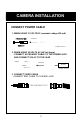
CAMERA INSTALLATION CONNECT POWER CABLE 1. WHEN USING 12 VOLTS DC (constant voltage 600 mA) POWER INPUT:RED CONNECT CENTER:(+) POWER SUPPLY 2. WHEN USING 24 VOLTS AC (40 Volt Amps) -CONNECT ACCESSORY CABLE TO THE POWER JACK AND CONNECT 24V AC TO THE LEAD POWER RED(+) CONNECT AC 24V BLACK:(-) POWER SUPPLY 3. CONNECT VIDEO CABLE -CONNECT BNC CABLE TO THE BNC JACK.
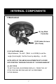
INTERNAL COMPONENTS 1. Mechanical (2) Joy Stick Controller (1) DC Auto iris Lens (2.8~11mm) (1) DC AUTO-IRIS LENS Adjust between TW (TELE WIDE) to set the angle (focal length) Set the focus by adjusting ∞N NOTE: BOTH OF THE ABOVE ADJUSTMENTS GET LOCKED INTO POSITION THROUGH THE USE OF "LOCKING HANDLES".
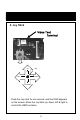
2. Joy Stick Video Test Terminal UP SET RIGHT LEFT DOWN Push the Joy stick for one second, and the OSD appears on the screen. Move the Joy Stick up, down, left & right to control the OSD functions.
Features SLC When the image is in front of strong background lighting, your camera allows you to get a clear image. INTENSIFIER 1/3 inch high density CCD and digital processor permit high quality pictures to be captured in very low light conditions. High Resolution Horizontal resolution of 540 TV lines is achieved by using a SONY Double Speed CCD with 410,000 pixels, yielding pictures with a high S/N ratio..
OSD All camera functions are menu driven for easy use. Dynamic Noise Reduction The Intensifier camera has a DSP chip that can remove image noise efficiently showing clean images in low light conditions. ELECTRONIC DAY/NIGHT The Intensifier camera can show color pictures in all lighting conditions, or you can have it automatically switch to a B/W picture in low light conditions MANUAL / AUTO IRIS LENS The Intensifier camera will work with auto iris, manual iris and fixed iris lenses.
Operating your camera OSD Function SETUP MENU LENS TYPE ●DC ●MANUAL SHUTTER TYPE ●OFF ●F/L ●MANUAL WHITE BALANCE ●ATW ●AWC MANUAL● SLC ●OFF ●LOW ●MIDDLE ●HIGH AUTO GAIN ●OFF ●LOW ●MIDDLE ●HIGH REDUCE NOISE ●OFF ●LOW ●MIDDLE ●HIGH INTENSIFIER ●AUTO ●OFF NEXT PAGE ●CAMERA TITLE ●DAY/NIGHT ●SYNC ●MOTION DET ●PRIVACY ●REVERSE ●DETAIL ●DEFAULT ●PAGE1 EXIT 11
Operating your camera – SETUP 1. Press the SET button (JOYSTICK) to access the SETUP mode. SET UP menu is displayed on the monitor screen. 2. Select the desired feature using the UP or DOWN button. Each time you press the UP or DOWN button, the arrow indicator moves up or down. Move the arrow indicator to the desired feature item. 3. Change the status of the selected feature using the LEFT or RIGHT button. If you press the RIGHT or LEFT button, the status will change.
Operating your camera – SETUP LENS 1) Setting up the LENS Select the lens type by pressing the RIGHT button. ① On the SETUP menu screen, move the arrow indicator to the lens using the UP or DOWN button. ② Select the desired feature using the LEFT or RIGHT button.
Operating your camera – SETUP LENS ▶When DC LENS selected, press SET button to control the BRIGHTNESS.
2) Shutter status and speed control You can control brightness of the screen by the shutter speed. ① Press the SET button to display the setup menu and move the arrow indicator to ‘SHUTTER’ using the UP or DOWN button. ② Set ‘SHUTTER’ to the desired mode using the LEFT or RIGHT button.
Operating your camera – SETUP SPEED CONTROL. ② ▶MANUAL : When setting the shutter speed manually.
▶ELC : You can control the BRIGHTNESS. ③When completed, press ‘SET’ Notes Avoid pointing the camera directly at a fluorescent lamp When the SHUTTER menu is set to FLK mode, the INTENSIFIER will not work.
Operating your camera – BACKLIGHT 3) SLC (Speco Light Compensation) - BACKLIGHT A built-in SR chip provides intelligent light level control to overcome severe Backlight conditions. ① Press the SET button to display the SETUP menu and move the arrow indicator to ‘BACKLIGHT’ using the UP or DOWN button. ② SET ‘BACKLIGHT’ to the desired mode using the LEFT or RIGHT button.
4) AUTO GAIN CONTROL (AGC) AGC allows a brighter picture in low light conditions. Higher GAIN level will yield a brighter screen but you might notice an increase in noise. ① Press the SET button to display the SETUP menu and move the arrow indicator to ‘AGC’ using the UP or DOWN button. ② SET ‘BACKLIGHT’ to the desired mode using the LEFT or RIGHT button.
Operating your camera – WHITE BALANCE 5) WHITE BALANCE ① Press the SET button to display the SETUP menu and move the arrow indicator to ‘WHITE BALANCE’ using the UP or DOWN button. ② Set ‘WHITE BAL.’ to the desired mode using LEFT or RIGHT button. ▶ ATW (Auto Tracking White Balance) : When color temperature is 2400~12000K, select this mode. (ex. A fluorescent lamp, outdoor). This is the best setting for most conditions.
▶MANUAL : To fine adjust, select the Manual mode. You can increase or decrease the red or blue factor while monitoring the difference on the screen. Set to ‘MANUAL’ mode and press the SET button. Increase or decrease the value for RED(R-Gain) and BLUE(B-Gain), watching the color of the picture, and press the SET button when you obtain the best color. Notes Proper White Balance may not be obtained under the following conditions in these cases select the AWC mode.
Operating your camera – REDUCE NOISE 6) REDUCE NOISE (Dynamic Noise Reduction) DNR reduces the noise on the screen. ① Press the SET button to display the SETUP menu and move the arrow indicator to ‘DNR’ using the UP or DOWN button. ② SET ‘REDUCE NOISE’ to the desired mode using the LEFT or RIGHT button.
Operating your camera – INTENSIFIER 7) INTENSIFIER Allows you to get clear images under night or low light conditions ① Press the SET button to display the SETUP menu and move the arrow indicator to ‘INTENSIFIER’ using the UP or DOWN button. ② SET ‘INTENSIFIER’ to the desired mode using the LEFT or RIGHT button. ▶ AUTO : When your camera is under night or low-lighting level, select this mode. This mode allows the camera to switch into B/W in low light conditions.
Operating your camera – CAMERA TITLE ① 8) NEXT PAGE ① Press the SET button to display the SETUP menu and move the arrow indicator to ‘SENCE UP’ using the UP or DOWN button. ② SET ‘NEXT PAGE’ to the desired mode using the LEFT or RIGHT button. (A) CAMERA TITLE ① Press the SET button to display the SETUP menu and move the arrow indicator to ‘CAMERA ID’ using the UP or DOWN button. ② SET ‘ON’ using the LEFT or RIGHT button.
Operating your camera – CAMERA TITLE ② ③ Press SET button to access the SETUP mode. ④ You can enter up to 15 characters. a. Move the cursor to character-enter location by using the LEFT or RIGHT button. b. Select the desired character by using the UP or DOWN button. c. Press SET button to confirm the blinking character. The first character is saved and the cursor in the bottom of the screen moves to the next position. d. Repeat steps a, b and c until you create the full name you want. e.
Operating your camera – COLOR / SYNC B) COLOR You can choose color and B/W mode electronically. ① Press the SET button to display the SETUP menu and move the arrow indicator to ‘SENCE UP’ using the UP or DOWN button. ② SET ‘INTENSIFIER’ to the desired mode using the LEFT or RIGHT button. ▶ COLOR : The camera will always display a color picture ▶ AUTO : The camera will switch into B/W mode under low light conditions.
C) SYNC Two SYNCHRONIZATION modes are available INTERNAL and EXTERNAL LINE-LOCK ① Press the SET button to display the setup menu and move the arrow indicator to ‘SYNC’ using the UP and DOWN button. ② SET to the desired mode using the LEFT or RIGHT button. ▶ INT : Internal synchronization ▶ L/L : If you choose ‘L/L’, you can adjust the desired phase. - Press the SET button. - You can adjust the desired phase from 0 to 270. Notes When it used in 24V AC power the L/L mode can be used.
Operating your camera – MOTION DETECTION D) Whenever your camera detects motion, THE WORDS “motion detected’ will appear on the screen. ① Press the SET button to display the setup menu and move the arrow indicator to ‘MOTION DET’ using the UP and DOWN button. ② SET ‘MOTION DET’ to the desired mode using the LEFT or RIGHT button. ▶OFF : Deactivation ▶ON : MOTION DET. Activated - Press SET button. - Move the arrow indicator to ‘AREA SET’ using UP and DOWN button, and then press the SET button.
Max. Min.
Operating your camera – PRIVACY E) PRIVACY To mask an area that you want to be private. ① Press the SET button to display the setup menu and move the arrow indicator to ‘PRIVACY’ using the UP and DOWN button. ② SET ‘PRIVACY’ to the desired mode using the LEFT or RIGHT button. ▶OFF : Deactivation ▶ON : PRIVACY mode activated -Press the SET button. -Move the arrow indicator to area you want to mask. -Set ‘ON’ using LEFT or RIGHT button.
Operating your camera – REVERSE F) REVERSE ① Press the SET button to display the setup menu and move the arrow indicator to ‘REVERSE’ using the UP and DOWN button. ② SET ‘REVERSE’ to the desired mode using the LEFT or RIGHT button. ▶OFF : Deactivation ▶ON : Reverse the image RIGHT or LEFT.
Operating your camera – DETAIL F) DETAIL ① Press the SET button to display the setup menu and move the arrow indicator to ‘DETAIL’ using the UP and DOWN button. ② SET ‘DETAIL’ to the desired mode using the LEFT or RIGHT button. ▶OFF : Deactivation ▶ON : DETAIL control mode (level 0~31) When the level is up, the sharpness will increase. Control this level to get your best picture quality. If the level is too high, you can get an unnatural image with video noise.
Operating your camera – DEFAULT / PAGE 1 G) DEFAULT : Use to reset your camera to FACTORY DEFAULT SETTING. H) PAGE 1 : PAGE 1 : Save the setting of NEXT PAGE function, and then move to SET UP menu.
Troubleshooting If you have trouble operating your camera, refer to the following Problem Nothing appears on the screen. Solution ● Check that the power cord and line connection between the camera and monitor are proper ● Check that you have properly connected VIDEO cable the camera VIDEO output jack. The image on the screen is dim. The image on the screen is dark. ● Is lens stained with dirt? Clean your lens with soft, clean cloth. ● Set the monitor to proper condition.
Problem Solution The color of the picture is not matched. ● Check that you have properly set the ‘ WHITE BALANCE ’ menu The image on the screen flickers. ● Is the camera facing to direct sunlight or fluorescent lighting? Change the camera position. L/L mode isn’t able to be selected. ● Have you connected your camera to DC power source? Connect it to AC power source.
SPECIFICATIONS ITEM CVC-6246IHR Power Source DC 12V & AC 24v ( Dual Voltage ) Power Consumption 230mA(DC) / 3.8W(AC) Image Sensor 1/3”, SONY SUPER HAD CCD, Total Pixels 811(H) x 508(V) , 1/3” CCD Effective Pixels 768(H) x 494(V) , 1/3” CCD LENS TYPE DC AUTO IRIS VAROFOCAL 2.8~11mm Maximum Aperture Ratio 1 : 1.3 ~2.0 Scanning System 2 : 1 Interlaced 525 Lines / 60 Fields / 30 Frames Synchronization Internal / Line Lock selectable Video Output 1.
DIMENSIONS * SIDE VIEW * TOP VIEW 38
WARRANTY 39
200 New Highway Amityville, NY 11701 631-957-8700 www.specotech.com VER. 070817 This manual is based on the date as shown in the right and specifications are subject to Change without notice for quality improvement.