HT7715DNV (Grey Housing) HT7715DNVW (White Housing) 560 Line Color Bullet Camera Weatherproof, Day/Night High Resolution Wall & Ceiling Mountable Please read this manual thoroughly before operation and keep it handy for further reference.
WARNING & CAUTION CAUTION RISK OF ELECTRIC SHOCK DO NOT OPEN CAUTION : TO REDUCE THE RISK OF ELECTRIC SHOCK DO NOT REMOVE COVER (OR BACK). NO US E R S E R V I C E A B L E P A RT S I N SIDE REFER SERVICING TO QUALIFIED SER V ICE PERSONNEL.
CONTENTS Package Contents 4 Precautions 5 Features 6 Camera Installation 7-11 LED Pattern 12 Specifications 13 Dimensions 14 Warranty 15 3
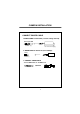
PACKAGE CONTENTS Please make sure that the following items are included in the package: 1 HT7715 Camera Series 3 Mounting Screws 1 Video test Connector 1 Wrench Please leave this manual with the end-user for future reference.
PRECAUTIONS • THIS CAMERA SHOULD BE ONLY INSTALLED BY QUALIFIED PERSONNEL • TO PREVENT A FIRE OR ELECTRICAL HAZARD PLEASE USE PROPER POWER CABLE • DO NOT CELAN THE COVER WITH AN ABRAISIVE CLEANING MATERIAL - PLEASE USE A SOFT CLOTH OR TISSUE TO CLEAN THE COVER • THERE ARE NO USER-SERVICEABLE PARTS INSIDE.
FEATURES • 1/3” SONY Super-Had HQ-1 , 560 TV lines of resolution • Spilt Glass Technology – avoids IR reflections • Auto iris DC Varifocal Lens (4mm – 9mm) • LUX level dip switch adjusts day/night settings to your requirements • Dual voltage operation • Video Test Connector for easy installation • Built-in 18 IR LEDs (80’ Range) and CDS sensor for day/night performance • Controls for BLC,ELC,F/L and L/L • Weatherproof operation • Built-in heater extends operating range and avoids condensation • Excellent
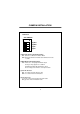
CAMERA INSTALLATION CONNECT POWER CABLE 1. WHEN USING 12 VOLTS DC (constant voltage 500 mA) Power Input :RED Center : (+) DC 12V Power Supply 2. WHEN USING 24 VOLTS AC (40 Volt Amps) RED(+) AC 24V BLACK:(-) Power Supply 3. CONNECT VIDEO CABLE -Connect BNC Cable To The BNC Jack.
CAMERA INSTALLATION Inner Controller Details 1.Function 2.V-Phase 3.Video Test 4.LUX Level 7.DC Lens Level 5.Zoom Controller 6.Heater 5.
CAMERA INSTALLATION 1.Function * DIP SWITCH ON OFF 1 (1)ELC 2 (2)BLC 3 (3)F/L 4 (4)L/L (1) ELC- Electronic Light Compensation ON : Camera is in Electronic Shutter Mode OFF: Electronic Shutter is fixed at 1/60 and Auto Iris mode is active (2) BLC-Back Light Compensation. BLC: If there is a strong light behind an object the object may appear as a shadow. Activating the BLC will minimize this effect. The Coverage of the BLC is center plus bottom.
CAMERA INSTALLATION 2. V-Phase Level (UP/Down) When desired, the vertical phase may be adjusted to synchronize the vertical phase of the camera with other cameras in the system. This feature is only available in 24 Volt AC operation 3. Video Test Connector Allows the connection of a Local Monitor to make initial adjustments to the camera 4. Lux Level Tells the camera when to switch to the B/W night mode. : Only one switch can be in the “on” position at a time.
CAMERA INSTALLATION COMPATIBILITY “A” type Box “B” type Box CVCTPEXT CVCTPLATE ★Original Mounting Flange Should be removed to use CVCTPLATE [CVCTPLATE Hole Description] Hole 1 : CVCTPEXT Hole 2 : Electrical Box “B” type Hole 3 : Electrical Box “A” type 11
LED PATTERN 4-9mm VF lens 18 Mini IR LEDs (80’ Range) 12
SPECIFICATIONS ITEM HT7715DNV Series Image Sensor 1/3” Sony Super-Had HQ-1 DSP CCD Resolution 560 TV Line Minimum illumination 0.03lux (IP Off) 0.00 LUX (IP on) Lens Type DC Auto Iris 4mm – 9mm (Varifocal) CDS Sensor Photoconductive Cells, Adjustable Electronic Shutter 1/60 – 1/1000,000 seconds Video Output 1.0vp-p into 75 ohms composite TV System NTSC Scanning System 2 : 1 Interlace Sync System Line Locked / Adjustable V-Phase.
DIMENSIONS Front View Side View 14
WARRANTY 15
200 New Highway Amityville, NY 11701 631-957-8700 www.specotech.com VER. 090509 This manual is based on the date as shown in the right and specifications are subject to Change without notice for quality improvement.