Installation and Operation Manual Digital Monitor Mark III ALL SPECIALTY CONCEPTS, INC. PRODUCTS, INCLUDING THIS ONE, CARRY A FIVE (5) YEAR LIMITED WARRANTY. Specialty Concepts, Inc. 8954 Mason Avenue, Chatsworth, CA 91311 USA Phone: (818) 998-5238 Fax: (818) 998-5253 Entire contents and all product names and part numbers Copyright 1995 Specialty Concepts, Inc.
TABLE OF CONTENTS Product Description......................1 Precautions.................................. 2 THANK YOU... ....for purchasing this Specialty Concepts product. As the world leader in electronics for the photovoltaic solar industry, we have put much time and effort into bringing you the best possible product at a reasonable price. We hope that you are extremely pleased with your new DM3, and with all of your Specialty Concepts products. Quick help....................................
PRECAUTIONS, WARNINGS, AND NOTES DANGER: Hydrogen gas is VERY explosive. Where there are batteries, there may be hydrogen. Work only in a well vented area. Make sure that no hydrogen is present when making or removing any electrical connections or when equipment is operating normally. Wires should have no power applied to them when making or removing connections to equipment in the presence of batteries. DANGER: Electricity, even low voltage electricity, can be dangerous.
QUICK SETUP IF YOU READ NO OTHER PAGE IN THIS MANUAL...READ THIS ONE! Page numbers after headings refer to the location in this manual where further details about the topic can be found. PLEASE READ ALL CAUTIONS AND WARNINGS ON PAGE 2 BEFORE PROCEEDING 1. Choose a location for the DM3 (Page 5): • This location must be indoors, or outdoors in a suitable enclosure, and protected from dirt, bugs, and moisture.
UNPACKING YOUR DM3 ADDITIONAL ITEMS AND TOOLS THAT YOU WILL NEED FOR INSTALLATION OF THE DM3 You will find the following items in the package: • The DM3 itself • This instruction manual • A small plastic bag containing the following items: -4 mounting screws -1 spare fuse -2 spare programming jumpers TO FLUSH MOUNT THE DM3: • Wire strippers • Drill with 3/8" bit • Keyhole saw or saber saw • Awl or punch • Slotted screwdriver • 2-conductor wire from DM3 to battery • 2-conductor wire (16-26 AWG) from remot
INSTALLATION INSTRUCTIONS 1. LOCATE A SUITABLE LOCATION. Page 12. This location must be protected from moisture, dust, dirt, and bugs. The DM3 MUST NOT be mounted out-of-doors unless it is installed in a suitable, COMPLETELY SEALED enclosure (available from your dealer). The DM3 may be mounted where other system components (batteries, inverters, etc.) are located or it may be mounted in a remote location many hundreds of feet from other equipment. 2. DECIDE ON WHAT WILL BE MEASURED. Page 13.
SELECTING WIRE SIZES Use the following information to determine what wire size you should use for various functions: TO CONNECT BATTERY POWER CONNECTIONS: You may use any size wire (16 to 20 AWG is best) that you find convenient. If the DM3 is more than 50 feet from the system’s batteries, use wire greater than 18 gauge. The larger the wire, the more accurate will be the voltage readings made by the DM3. TO CONNECT AUX. INPUT: You may use any size wire for this input.
OPERATING INSTRUCTIONS 1. TURNING ON THE DM3: Once connected to a source of power (the batteries), the DM3 will always be on. Power consumption is very low , so no impact will be experienced to the capacity of the system. To turn off the DM3, you must remove battery power or remove the fuse. 2. SELECTING A FUNCTION: Set the FUNCTION SELECT knob to the item you wish to measure.
SPECIFICATIONS PARAMETER VALUE Operating voltage range............................................................. 9 volts to 65 volts continuous, 85 volts for 1 minute. Current measurement, internal shunt (NOTE 1) ............................ 30 amps Current measurement, external shunt (NOTE 2) ............................ Up to 999 amps Operating temperature range..................................................... 32° F to 122° F (0° C to 50° C) Current consumption 1.
TROUBLE SHOOTING DISPLAY BLANK, ALARMS DO NOT FUNCTION, NO POWER TO UNIT 1) Re-check system wiring to insure proper installation and battery polarity . 2) Check all system fuses and circuit breakers. Before replacing a blown fuse, locate and correct the cause of the blown fuse. 3) Check the fuse on the DM3. If it is blown, it indicates that the DM3 probably needs service. 4) Confirm that all system connections are clean and tight.
PROGRAMMING PIN INSTRUCTIONS The decimal point programming pins are factory set for the internal 30 amp shunt or for use with the external 100 amp shunts. You only need to reprogram the decimal point if you are using the 500 or 1000 amp external shunt. To perform this reprogramming, remove the programming jumper from the set of pins that correspond to the input that the shunt is connected to. If you are using two shunts, remove both programming pins. IF YOU HAVE AN ACCURATE DIGITAL VOLTMETER (DVM)...
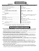
DM 3 COMPONENT LOCATIONS AND FUNCTIONS ALARM PROGRAMMING PINS DECIMAL POINT PROGRAMMING PINS HI ALARM SET LO ALARM SET FUSE 1 AMP TYPE AGC MOUNTING LOCATION FOR OPTIONAL RELAY OR BEEPER MODULES INTERNAL 30 AMP SHUNT (UNDER BOARD). CUT FOR EXT. SHUNT ONLY. AUX. INPUT SCALE SELECT REMOVE THIS JUMPER WHEN USING CURRENT 2 + - AUX.
MOUNTING METHODS FLUSH MOUNT OPTIONAL METAL ENCLOSURE ALT. WIRE ROUTING CUTOUT IN WALL DM3 PLATE USE TEMPLATE IN MANUAL FOR CUTOUT DM3 MOUNTING SCREWS CABLE CLAMP OR CONDUIT HUB* WIRES OR CONDUIT* WALL - FRONT VIEW WALL - END VIEW SURFACE MOUNT ALT.
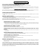
SOLAR PANELS + + P A N E L - P A N E L + B A T T + - DM3 REGULATOR* B A T T - ALTERNATE WIRE ROUTING METHOD (FOR USE WITH OPTIONAL ENCLOSURE) - + INVERTER OR LOAD + - SHUNT BATTERIES DM3 WIRING DIAGRAM #1 Shown using internal shunt for current 1, external shunt for current 2 * Suggested hookup with SCinc ASC regulator shown. Other regulators may be used.
LIMITED FIVE YEAR WARRANTY SPECIALTY CONCEPTS, INC. 1. Specialty Concepts, Inc. warrants all its products for a period of five (5) years from the date of shipment from its factory. This warranty is valid against defects in materials and workmanship for the five (5) year warranty period. It is not valid against defects resulting from, but not limited to: A. Misuse and/or abuse, neglect or accident. B. Exceeding the unit's design limits. C.