
Install Sheet

email@windonbay.com 02.22.19
|
92-WB-RTG-02
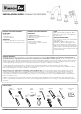
INSTALLATION GUIDE: ROMAN TUB GROUPING
SPOUT MOUNT
WASHER & NUT
SPOUT TEE
RETAINING CLIP
TUB SPOUT INSTALLATION
2
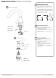
HANDLE
BUTTON
SET SCREW
FLANGE
MOUNT NUT
MOUNT WASHER
VALVE INSTALLATION
3
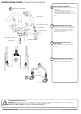
TURN OFF WATER SUPPLIES.
Ensure mounting holes are as follows:
• Four (4) Holes; Ø 1-1/4" Min to Ø 1-5/8"
Max.
• Center distance between holes 3” min, (6”
Min between Hot and Cold valve assemblies).
• Side spray holder hole location should be a
minimum distance of 4” from Hot or Cold valve
to assure handle lever clearance
• Surface thickness = 1” Max
1
TUB SPOUT INSTALLATION:
• Remove Retaining Clip from Spout Shank.
• Remove Spout Tee, Mounting Nut, and
Washer from Spout Shank.
• Assemble Spout to surface.
• Re-assemble Washer and Mounting Nut and
tighten to surface.
• Re-assemble Spout Tee and Retaining Clip.
2
VALVE INSTALLATION:
• Remove Handle and Flange from Valve
assemblies.
• From below, insert bodies with Mount Nuts
and Washer in surface holes.
• Assemble Valve Flanges onto bodies hand
tighten.
• Tighten body Mount Nuts and Screws to
secure valve bodies.
• Assemble Handles, Screws, and Buttons to
mounted valves.
3
1
1
4
"
MIN
1
5
8
"
MAX
6”
3” MIN 4” MIN