
Installation Guide

INSTRUCTIONS FOR MODELS
92-STW-SC2-01
For additional assistance or service please contact:
SPEAKMAN
®
Company
400 Anchor Mill Road
New Castle, DE 19720
800-537-2107
customerservice@speakman.com
www.speakman.com
STW-SC2
Cabinet for Medium
Thermostatic Mixing Valve
(STW-362)
HELPFUL TOOLS & SUPPLIES:
TOOLS AND SUPPLIES
Level Measuring
Tape
Stud Finder
Utility
Knife
Safety
Glasses
Caulk Gun
Pencil
Mounting Hardware
(not included)
Phillips
Screwdriver
Keyhole
Saw
Be sure to wear eye protection.
SAFETY TIPS
IMPORTANT
• Ensure the mounting structure and mounting
hardware can safely support the product in use.
• Do not over-tighten any connections or damage
may occur.
• Be sure to read instructions thoroughly before
beginning installation.
Warranty information can be found at:
www.speakman.com
WARRANTY
Your new Speakman Product is designed for years
of trouble-free performance. Keep it looking new by
cleaning it periodically with a soft cloth. The use of
harsh chemicals and abrasives on any of the
Speakman custom finish products may damage the
finish and void the product warranty. Please be
sure to only use approved cleaners. Please contact
Speakman for any clarification of acceptable
cleaners.
MAINTENANCE
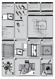
1 SURFACE MOUNTED CABINET
SKIP TO STEP 5
Determine desired mounting position of Cabinet and Valve. Ensure mounting location and mounting hardware are
capable of supporting the product in use. Mark the seven (7) mounting locations onto surface.
4"
102mm
22mm
8
"
3
73
20mm
7X
"
2"
51mm
51mm
2"
6"
508mm
152mm
20"
203mm
5
7
194mm
"
8
85mm
508mm
20"
7X
4
8"
"
8
3
7X
R
3
16
"
6mm
2 RECESS MOUNTED CABINET
24"
610mm
24"
610mm
Ensure proper mounting structure is present within the
wall cavity. Measure and cut out wall opening using
appropriate tools.
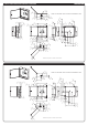
3
Insert the Cabinet in the rough in opening.
Make sure it is level. If it doesn’t fit, adjust the
hole opening.
4
Knock out required holes to secure Left Side
of Cabinet and Right Side of Cabinet to wall
with eight (8) 1/4" fasteners properly anchored
(supplied by installer). Ensure the mounting
surface (wall, etc.) and mounting hardware
can safely support the product in use.
5
Install mounting hardware through the seven (7)
mounting locations into a secure brace (supplied
by installer) or into wall. This will support the
Valve. Ensure the mounting structure and
mounting hardware can safely support the
product in use.
6
Position the Valve (1) above the Support Bracket
within the Cabinet.
7
Insert Valve into Mounting Bracket as shown below. Ensure Valve is fully seated into bracket.
8
If the Cabinet is recess mounted, install the
Flange Trim and Caulk it in place.