
Installation Guide

PAGE 2 09/10
92-3141
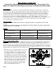
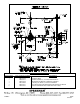
2) Slip the rough-in template over the valve control spindle. If the opening in the wall is smaller than the outside
diameter of the template, trace the outside diameter of the template, remove the template, and recut the opening in
the wall. Slip the template onto the valve again until the template bottoms out on the top of the valve bonnet (See
Figure 2). Note- When installing a valve with the built-in volume control/diverter feature, make sure the template is
positioned so the brass “VC/DIV” spindle is in the relieved area of the template. The finished wall should fall
between the minimum and maximum limits of the template if the valve has been installed properly. Leave the
template in place if the finished wall has to be installed. The template will insure the proper size opening for repair
accessibility, as well as protect the valve from damage during the finished wall installation.
3)
Install the rough piping and transfer valve (If applicable) to the shower and/or tub outlets of the valve. If the
installation is only using one outlet, be sure to plug the other outlet with the provided pipe plug. Check connections
for leaks. If applicable, construct the finished wall.
4) With the necessary opening(s) in the finished wall, assemble the accessory(s) to the rough piping (Important-
See
separate “Accessory Installation Instructions” supplied with some of the accessories). With the rough-in template
removed & the valve turned OFF, turn both the hot & cold water supplies ON. Using the handle, operate the valve
checking all the connections for leaks.
5)
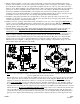
The maximum hot water temperature setting adjustment (Temperature Limit Stop (TLS)) of the valve has been
factory set at 110° F. Important- Check each valve installation with a thermometer to make sure the
maximum hot water temperature is set to the recommended setting of 110° F maximum. To lower the limit of
the maximum hot water temperature the valve delivers, adjust the valve’s temperature limit stop (TLS) plate (See
Figure 3). Slip the retaining o-ring and the TLS plate towards the end of the spindle. Rotate the valve handle
counter clockwise to the maximum desired hot water temperature. Position the TLS plate so it contacts the TLS
ring lug on the top of the valve’s cartridge and therefore restricts the counter clockwise rotation of the handle.
Handle can be moved slightly, so TLS plate slips into place. Slip the retaining o-ring back into the groove of the
spindle. Turn off the valve and remove the handle.
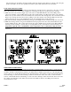
6)
Note- For valve with built-in volume control/diverter feature, make sure the brass “VC/DIV” spindle is in the center
position (spindle flats in the vertical position).
Slip the trim sleeve onto the spindle and valve. Make sure the sleeve legs are position between the ribs of the black
bonnet. Apply clear silicone sealant to the backside outer flat surface of the wall plate. Basic Valve
- Position the
wall plate so that the 3/8 diameter hole is in the 12 o’clock position. Carefully slip the wall plate onto the trim
sleeve. Valve w/VC/DIV
- Position the wall plate and slide “VC/DIV” spindle tube onto the “VC/DIV” spindle of
the valve. Carefully slip the wall plate onto the trim sleeve. Properly position against the finished wall. Fasten the
wall plate to the valve using the valve using the (2) long wall plate screws. Make sure the wall plate hole is centered
with the trim sleeve. Do not over tighten the wall plate screws.
Wipe off any excess sealant from around the outer
edge of the wall plate. Remove clear protective sheet from top of index plate (If applicable). Slip the index plate
over the trim sleeve and position the small hole in the index plate onto the wall plate index pin. Holding the index
plate in position, slip the index retaining ring over the trim sleeve and insert the tabs (2) of the ring into the wall