
Installation Sheet
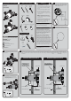

6 CPV-TP ONLY
If your installation is for a shower only, apply thread
seal tape to the lower outlet port and install the included
cap. Wrench tighten.
7
Ensure Valve is positioned plumb and level.
Remove Rough-In Template from Valve. Make
threaded connections or plumb and solder all
joints and fittings. Take care to protect
surrounding area when soldering. Secure piping
to surrounding structure.
OR
8
Make piping connections for all accessories.
Take care to protect surrounding area when
soldering. Secure piping to surrounding
structure.
OR
9
Reinstall the Integral Stops using a Socket
Wrench equipped with a 9/16” Deep Well
Socket or Crescent Wrench.
Socket
Wrench
9/16”Deep Well
Socket
+
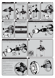
10
If your Shower Valve is equipped with an
integral diverter, reinstall the Diverter
Cartridge taking care to align mounting posts
of cartridge with the corresponding holes in
the diverter valve body. Install Diverter Nut
and tighten with a Socket Wrench and
13/16” Deep Well Socket. Take care to not
over-tighten connections.
Socket
Wrench
+
13/16”Deep Well
Socket
11
If you are performing a Standard
Installation, please proceed to Step 14
If you are performing a Back to Back
Installation, or have reversed inlet
supplies, please proceed to Step 12
Your Shower Valve has the ability to be mounted
back-to-back with another Valve in a shared
space. This means the hot and cold inlets may
be reversed. Please see the following steps to
adapt your valve for back-to-back mounting or
reversed inlet supplies.
OR
BACK-TO BACK INSTALLATION STEP 1
To adapt your shower valve for back to back installation, use an adjustable wrench to unthread and remove the Bonnet
❶. Then remove Cartridge Assembly ❷, and Bonnet O-Ring ❸ from valve body.
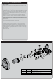
12
Rotate Valve Cartridge ❷180˚ and reinstall into Valve Body taking care to properly align the mounting posts of the
Cartridge with the corresponding holes within the Valve. The “H” marking on Valve Cartridge cover should now be on
the right hand side. Reinstall Bonnet ❶ , making sure the Large Bonnet O-Ring ❸ is in place within the Valve Body.
ROTATE
180˚
BACK TO BACK INSTALLATION STEP 213
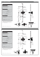
14
Ensure the Valve is in the “OFF” position. Turn “ON” water supplies and check all connections for leaks.
The maximum hot water temperature setting adjustment (Temperature Limit Stop (TLS)) of the valve has
been factory set at 110° F. Important- Check each valve installation with a thermometer to make sure
the maximum hot water temperature is set to the recommended setting of 110° F maximum. To lower
the limit of the maximum hot water temperature the valve delivers, adjust the valve’s temperature limit
stop (TLS) plate.
• Slip the retaining O-ring and the TLS plate
towards the end of the spindle.
• With the water supplies on, rotate the
valve spindle clockwise to the maximum
desired hot water temperature.
• Position the TLS plate so it contacts the lug
and therefore restricts the clockwise rotation
of the spindle.
• Slip the retaining O-ring back into the
groove of the spindle to hold the TLS plate in
place.
• Rotate the spindle counter-clockwise to the
“Off” position.
TEMPERATURE LIMIT ADJUSTMENT
LUG
TLS PLATE
O-RING
15
16
Reinstall Rough-In Template over Valve to protect it during final wall preparation.