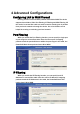
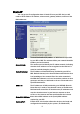
4 Advanced Configurations Configuring LAN to WAN Firewall Filtering function is used to block packets from LAN to WAN. The device supports three kinds of filter Port Filtering, IP Filtering and MAC Filtering. All the entries in current filter table are used to restrict certain types of packets from your local network to through the device. Use of such filters can be helpful in securing or restricting your local network.
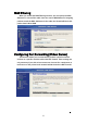
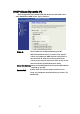
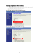
MAC Filtering When you enable the MAC Filtering function, you can specify the MAC Addresses in current filter table. Once the source MAC Address of outgoing packets match the MAC Addresses in the table, the firewall will block this packet from LAN to WAN. Configuring Port Forwarding (VirtualʳServer) This function allows you to automatically redirect common network services to a specific machine behind the NAT firewall.
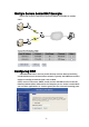
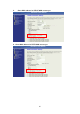
Multiple Servers behind NAT Example: In this case, there are two PCs in the local network accessible for outside users. Configuring DMZ A Demilitarized Zone is used to provide Internet services without sacrificing unauthorized access to its local private network. Typically, the DMZ host contains devices accessible to Internet traffic, such as Web (HTTP) servers, FTP servers, SMTP (e-mail) servers and DNS servers. So that all inbound packets will be redirected to the computer you set.
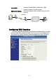
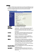
Enable DMZ: DMZ Host IP Address: Enable the “Enable DMZ”, and then click “Apply Changes” button to save the changes. Input the IP Address of the computer that you want to expose to Internet. Configuring WAN Interface The device supports four kinds of IP configuration for WAN interface, including Static IP, DHCP Client, PPPoE and PPTP. You can select one of the WAN Access Types depend on your ISP required. The default WAN Access Type is “Static IP”.
Static IP You can get the IP configuration data of Static-IP from your ISP. And you will need to fill the fields of IP address, subnet mask, gateway address, and one of the DNS addresses. IP Address: Subnet Mask: Default Gateway: DNS 1~3: The Internet Protocol (IP) address of WAN interface provided byʳyour ISP or MIS. The address will be your network identifierʳ besides your local network.
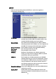
DHCP Client (Dynamic IP) All IP configuration data besides DNS will obtain from the DHCP server when DHCP-Client WAN Access Type is selected. DNS1~3: The IP addresses of DNS provided by your ISP. DNS (Domain Name Server) is used to map domain names to IP addresses. DNS maintain central lists of domain name/IP addresses and map the domain names in your Internet requests to other servers on the Internet until the specified web site is found.
PPPoE When the PPPoE (Point to Point Protocol over Ethernet) WAN Access Type is selected, you must fill the fields of User Name, Password provided by your ISP. The IP configuration will be done when the device successfully authenticates with your ISP. User Name: Password: Connect Type: The account provided by your ISP The password for your account.
PPTP Point to Point Tunneling Protocol (PPTP) is a service that applies to connections in Europe only IP Address: The Internet Protocol (IP) address of WAN interface provided by your ISP or MIS. The address will be your network identifier besides your local network. Subnet Mask: The number used to identify the IP subnet network, indicating whether the IP address can be recognized on the LAN or if it must be reached through a gateway.
Configuring Clone MAC Address The device provides MAC address clone feature to fit the requirement of some ISP need to specify the client MAC address. Physical WAN interface MAC Address clone 1. Clone MAC address for DHCP Client WAN access type 2.
3. Clone MAC address for PPPoE WAN access type 4.
5. Physical LAN interface MAC address clone Configuring DHCP Server 1. To use the DHCP server inside the device, please make sure there is noʳ OtherʳDHCP server existed in the same network as the device. 2. Enable the DHCP Server option and assign the client range of IP addresses as following page. 3. When the DHCP server is enabled and also the device router mode is enabled then the default gateway for all the DHCP client hosts will set to the IP address of device.
Bandwidth Control This functionality can control Bandwidth of Up/Downstream 1. Enable Bandwidth Control and then enter Data RateΕLatency and Burst Packet in the specific field. Note: Only device on Client mode or WISP mode this functionality can take effective. 2. Parameter Definition Label Description Upstream Data Rate Speed of transmit data that from Ethernet interface to Wireless interface.
QoS (Quality of Service) Filter Priority and IP-ToS have not finished yet and also fine tuning. QoS allows you to specify some rules, to ensure the quality of service in your network. Such as use Bandwidth Priority concept to allocate bandwidth. This function can be helpful in shaping and queuing traffic from LAN (WLAN) to WAN or LAN to WLAN, but not WLAN to WLAN.
1. Enable QoS and enter Max Throughput (default 20Mbps) ଞ Bandwidth Ratio (default H:50%, M:30%, L:20%) The following table describes the labels in this part. Label Description QoS Enabled Select this check box to enable quality of service. Bandwidth Borrowed Select this check box to allow a rule to borrow unused bandwidth. Bandwidth borrowing is decided by priority of the rules. Higher priority will get the remaining bandwidth first.
2. QoS Rule settings Label Description IP Address Enter source/destination IP Address in dotted decimal notation. Netmask Once the source/destination IP Address is entered, the subnet mask address must be filled in this field. MAC Address Enter source/destination MAC Address. Port / range You can enter specific port number or port range of the source/destination Protocol Select a protocol from the drop down list box. Choose TCP/UDP, TCP or UDP.
Current QoS setting table In this part, you can see how many rules have been specified. And you can see the detail about the rules and manage the rules. This table can input 50 rules at most. An example for usage User C LAN WAN VoIP FTP Internet Web User B Zplus-G192 User A For example, there are three users in your network. ɿ User A wants to browse the websites to retrieve information. ɿ User B wants to use FTP connection to download a large file.
Static Route Setup User can set the routing information let the Router knows what routing is correct also it can not learn automatically through other means. For example, if user wants to link the Network 3 and Network 4 separately from Network 1 that Routing Table configuration as blow: 1. Enable Static Route in Route Setup of TCP/IP page and then enter IP Address of Network 3ଞSubnet Mask and IP Address of Router (R1) in Default Gateway field final click Apply Change button.
2. Enter IP Address of Network 4ଞSubnet Mask and IP Address of Router (R2) in Default Gateway field final click Apply Change button. 3. In Static Route Table there have two routings for Network 3 and Network 4 Dynamic Route Setup The Dynamic Route utilizes RIP1/2 to transmit and receive the route information with other Routers. 1. Enable Dynamic Route and then select RIP 1ΕRIP2 or Both to transmit/receive packets final click Apply Change button. 2.
3. In Dynamic Routing Table there have two routings for Network 3 and Network VPN Pass-through This functionality let the device can Pass-through the VPN packets including PPTP/ L2TP/IPsec VPN Connection. VPN Connection LAN Laptop 1 VPN Client WAN (VPN Passthrough) VPN Server 1. Check the VPN Pass-through in WAN Interface of TCP/IP Page that you want and then click Apply Changes button.
Using CLI Menu Start a SSH(Secure Shell) client session to login the device The SSH server daemon inside device uses well-known TCP port 22. User must use SSH client utility such like Putty to login the device. The default password for user “root” is “qwert”, once user login the device then can change the password by CLI command. Execute CLI program This program won’t execute automatically when user login the device. User must manually execute it by typing the case-sensitive command “cli”.
SNMP Agent This device is compatible with SNMP v1/v2c and provide standard MIB II. Currently only the “public” community string is available and the modified settings by SNMP SET request will be lost after rebooting the device. 1. Enable SNMP and then enter IP Address of SNMP Manager in Trap Receiver IP Address field and Community String in System Community String field. Final click Apply Changes button. 2.
Traps Description coldStart(0) The trap from device after reboot the device linkDown(2) The trap is sent when any of the links are down. See the following table. linkup(3 The trap is sent when any of the links are UP. See the following table. authenticationFailure(4) The trap is sent when the device receiving gets or sets requirement with wrong community. 4. Private MIBs OID Description 1.3.6.1.4.1.99.1 Mode, Operation Mode in device. 1.3.6.1.4.1.99.2 SSID, SSID of the device 1.3.6.1.4.1.99.
1.3.6.1.4.1.99.3 - Channel 1.3.6.1.4.1.99.4 - Band 1.3.6.1.4.1.99.5 - RSSI 1.3.6.1.4.1.99.6 - Active_Clients 1.3.6.1.4.1.99.7 - Active_Clients_List 1.3.6.1.4.1.99.
Firmware Upgrade Firmware Types The firmware for this device is divided into 2 parts, one is web pages firmware the other is application firmware, and the naming usually are g120webpage.bin and g120linux.bin. To upgrade firmware, we suggest user first upgrade the application firmware then web pages firmware. Upgrading Firmware The Web-Browser upgrading interface is the simplest and safest way for user, it will check the firmware checksum and signature, and the wrong firmware won’t be accepted.
Configuration Data Backup & Restore Rest Setting to Factory Default Value Since the device is designed for outdoor used, there is no interface outside the housing to reset the configuration value to the factory default value. The device provides the Web-Browser interface to rest the configuration data. After resetting it, the current configuration data will be lost and restored to factory default value.
1. Discover After press this button, you could see there are how many devices in your network. And you would see the basic information about these devices, such as: ɿ SSID ɿ IP Address ɿ Subnet Mask ɿ Channel number ɿ MAC Address ɿ Active Client: this field shows how many clients associated with the device ɿ RSSI: this field shows Received Signal Strength I indication while device is on AP-Client mode 2. Setup IP After you press the Setup IP button, you would see Setup IP Address window.
3. Detail. If you want to see more detailed information, you could press the Detail button, and then you would see the Detail Information window. 4.
5. Active Clients After press Active Clients button, you would see WLAN AP Active Clients window. In this window, you could see client’s information, such as: 6. Connect to Web Server If you want connect to device’s web server, you could press this button, or double-click on the device. 7. Close You could press this button to leave this tool.