OA200 Outdoor 802.11ag AP Quick Installation Guide Version 1.
Content 1. Introduction .......................................................... 3 2. Operating Mode.................................................... 4 3. Hardware Installation........................................... 6 4. Quick Setup Guide............................................... 11 5. Waterproof RJ-45 Connector Assembly ...........
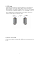
1. Introduction 1.1 Purpose This document provides information and procedures on hardware installation, setup and management of the IEEE 802.11ag AP Bridge. 1.2 Overview Access Point with Rugged Housing for Application OA200 Wireless11ag AP Bridge provides quality connectivity for Wi-Fi networks. This device is ideal for rugged environments and application. Multiple Operating Modes OA200 Wireless11ag AP Bridge provides 3 operating modes. There are AP, AP Repeater and Wireless Client.
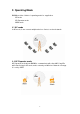
2. Operating Mode OA200 provides 3 kinds of operating mode for application. AP mode AP Repeater mode WDS mode 2.1 AP mode In AP mode, it can connect multiple wireless clients to a wired network. 2.2 AP Repeater mode AP Repeater mode allows OA200 to communicate with other 802.11ag APs while functioning in AP mode, and to extend your Wireless Network coverage.
2.3 WDS mode In this mode, it allows wireless connection between two or more wired and wireless networks, such as two networks with the same sub-network in different buildings. For building-to-building wireless connection, each building should implement one OA200 as WDS. In this case, the OA200 can act as a wireless bridge between the two wired and wireless networks. Please fill in remote AP’s MAC address in “WDS links” space. 2.
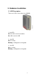
3. Hardware Installation 3.1 LED Description There are 3 LEDs on the right side of OA200. 1. LInk LED Off: No LAN connection available On: LAN connection OK 2. 11g LED Off: no activity Blinking: sending and receiving data 3.
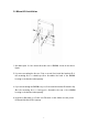
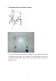
3.2 Mount Kit Installation 1. Assemble part 1 of the mount kit at the rear of OA200, shown in the above figure. 2. If you are mounting the Access Point on a wall, first install the bracket 2 of the mounting kit to a suitable position. Assemble the back of the OA200 housing to the bracket subsequently. 3. If you are mounting the OA200 to a pole, first install the bracket 2 and the clip 3 of the mounting kit to a strong pole. Assemble the rear of the OA200 housing to the bracket subsequently. 4.
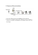
3.3 Power over Ethernet Installation 1. Connect the Ethernet cable from the OA200 to PoE hub (LAN out). 2. Connect a second Ethernet cable from the LAN-IN port of the PoE adapter to a free port of a switch or hub within the local network. Please refer to the above figure.
3.4 Hardware Reset to default settings You can reset the wireless bridge unit’s settings to factory defaults by pushing reset button using reset bar. The reset button is located and hidden inside of the rear panel as above figure. Please refer to the following steps to perform the Hardware Reset.
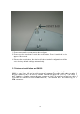
1. Please unscrew the screw part as above figure. 2. Please use the reset bar to reach the reset button. Press it and hold on for approx 10 seconds. 3. Release the reset button, the device will reboot and all configurations will be set to factory default settings automatically. 3.5 Antenna installation on OA200 antenna box, so is necessary for cabl this unit. O A200 i sinside one 11ag APthe serexternal i es wi t hantenna ext er nal ant enna.
4. Quick Setup Guide AP Default Settings The default settings are shown as the following: User Password IP Address Subnet Mask RF ESSID Channel Mode Encryption admin 192.168.1.250 255.255.255.
Step1 START UP & LOGIN In order to configure the OA200, you must use your web browser and manually input http://192.168.1.250 into the Address Box and press Enter. The Main Page will appear. To start configure the OA200, you must input password “admin” on the password section. Once you have logged-in as administrator, it is ideal to change the administrator password to ensure a secure protection to the Wireless 11ag AP.
Step2 Local Area Network: This is OA200 IP Address and Subnet Mask as seen on the internal LAN. The default value is 192.168.1.250 for IP Address and 255.255.255.0 for Subnet Mask. Please Click “Apply” button to save your settings once you have any change.
Step3 Please select the antenna for each band. After completed the setting and hardware installation, please adjust the direction of OA200 to remote site OA200 for a high quality transmission.
5. Waterproof RJ-45 Connector Assembly Recommendation: Please prepare one CAT-5 or better quality Ethernet cable then get through the parts of waterproof connector before this assembly.
The equipment has been tested and found to comply with FCC and CE Rules.Operation is subject to the following two conditions: (1) This device may not cause harmful interference. (2) This device must accept any interference received including interference that may cause undesired operation. REMARK: 5150MHz~5250MHz, 5250MHz ~ 5350MHz frequency will be disabled by firmware.
Federal Communication Commission Interference Statement This equipment has been tested and found to comply with the limits for a Class B digital device, pursuant to Part 15 of the FCC Rules. These limits are designed to provide reasonable protection against harmful interference in a residential installation. This equipment generates uses and can radiate radio frequency energy and, if not installed and used in accordance with the instructions, may cause harmful interference to radio communications.