
User's Manual
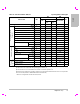


Table Of Contents
- M-Turbo Ultrasound System User Guide
- Contents
- Introduction
- Chapter 1: Getting Started
- Chapter 2: System Setup
- Displaying the setup pages
- Restoring default settings
- A & B Key, Footswitch setup
- Administration setup
- Annotations setup
- Audio, Battery setup
- Cardiac Calculations setup
- Connectivity setup
- Date and Time setup
- Display Information setup
- IMT Calculations setup
- Network Status setup
- OB Calculations setup
- OB Custom Measurements setup
- OB Custom Tables setup
- Presets setup
- System Information setup
- USB Devices setup
- Chapter 3: Imaging
- Chapter 4: Measurements and Calculations
- Chapter 5: Troubleshooting and Maintenance
- Chapter 6: Safety
- Ergonomic safety
- Electrical safety classification
- Electrical safety
- Equipment safety
- Battery safety
- Clinical safety
- Hazardous materials
- Electromagnetic compatibility
- ALARA principle
- Acoustic artifacts
- Guidelines for reducing MI and TI
- Output display
- Transducer surface temperature rise
- Acoustic output measurement
- Acoustic output tables
- Labeling symbols
- Chapter 7: References
- Chapter 8: Specifications
- Glossary
- Index

Chapter 7: References 139
References
Chapter 7: References
Measurement accuracy
Themeasurementsprovidedbythesystemdo
notdefineaspecificphysiologicaloranatomical
parameter.Rather,themeasurementsareofa
physicalproperty suchasdistanceforevaluation
bytheclinician.Theaccuracyvaluesrequirethat
youcanplacethecalipersoveronepixel.The
valuesdonotincludeacousticanomalies
ofthe
body.
The2Dlineardistancemeasurementresultsare
displayedincentimeterswithoneplacepastthe
decimalpoint,ifthemeasurementistenor
greater;twoplacespastthedecimalpoint,ifthe
measurementislessthanten.
Thelineardistancemeasurementcomponents
havetheaccuracyandrangeshown
inthe
followingtables.
Table 1: 2D Measurement Accuracy and Range
2D Measure
Accuracy
and Range
System
Tolerance
a
Accuracy
By
Test Method
b
Range (cm)
Axial
Distance
< ±2% plus
1% of full
scale
Acquisition Phantom 0-26 cm
Lateral
Distance
< ±2% plus
1% of full
scale
Acquisition Phantom 0-35 cm
Diagonal
Distance
< ±2% plus
1% of full
scale
Acquisition Phantom 0-44 cm
Area
c
< ±4% plus
(2% of full
scale/smallest
dimension) *
100 plus 0.5%
Acquisition Phantom 0.01-720
cm
2
Circumfer-
ence
d
< ±3% plus
(1.4% of full
scale/
smallest
dimension) *
100 plus 0.5%
Acquisition Phantom 0.01-96
cm
a. Full scale for distance implies the maximum depth of the
image.
b. An RMI 413a model phantom with 0.7 dB/cm MHz attenuation
was used.
c. The area accuracy is defined using the following equation:
% tolerance = ((1 + lateral error) * (1 + axial error) – 1) * 100 +
0.5%.
d. The circumference accuracy is defined as the greater of the
lateral or axial accuracy and by the following equation:
% tolerance = ( (maximum of 2 errors) * 100) + 0.5%.
2