
User's Manual
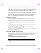
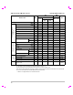


Table Of Contents
- M-Turbo Ultrasound System User Guide
- Contents
- Introduction
- Chapter 1: Getting Started
- Chapter 2: System Setup
- Displaying the setup pages
- Restoring default settings
- A & B Key, Footswitch setup
- Administration setup
- Annotations setup
- Audio, Battery setup
- Cardiac Calculations setup
- Connectivity setup
- Date and Time setup
- Display Information setup
- IMT Calculations setup
- Network Status setup
- OB Calculations setup
- OB Custom Measurements setup
- OB Custom Tables setup
- Presets setup
- System Information setup
- USB Devices setup
- Chapter 3: Imaging
- Chapter 4: Measurements and Calculations
- Chapter 5: Troubleshooting and Maintenance
- Chapter 6: Safety
- Ergonomic safety
- Electrical safety classification
- Electrical safety
- Equipment safety
- Battery safety
- Clinical safety
- Hazardous materials
- Electromagnetic compatibility
- ALARA principle
- Acoustic artifacts
- Guidelines for reducing MI and TI
- Output display
- Transducer surface temperature rise
- Acoustic output measurement
- Acoustic output tables
- Labeling symbols
- Chapter 7: References
- Chapter 8: Specifications
- Glossary
- Index

104
combinationhasitsownuniquecharacteristicacousticoutput,andwillnotmatchthenominal
outputonwhichthedisplayestimatesarebased.Thisvariabilitybetweensystemsand
transducersintroducesanerrorintodisplayedvalue.Bydoingacousticoutputsampling
testingduringproduction,theamountoferrorintroducedbythevariabilityis
bounded.The
samplingtestingensuresthattheacousticoutputoftransducersandsystemsbeing
manufacturedstayswithinaspecifiedrangeofthenominalacousticoutput.
Anothersourceoferrorarisesfromtheassumptionsandapproximationsthataremadewhen
derivingtheestimatesforthedisplayindices.Chiefamongtheseassumptionsis
thatthe
acousticoutput,andthusthederiveddisplayindices,arelinearlycorrelatedwiththetransmit
drivevoltageofthetransducer.Generally,thisassumptionisverygood,butitisnotexact,and
thussomeerrorinthedisplaycanbeattributedtotheassumptionofvoltagelinearity.
Related guidance documents
InformationforManufacturersSeekingMarketingClearanceofDiagnosticUltrasound
SystemsandTransducers,FDA,1997.
MedicalUltrasoundSafety, AmericanInstituteofUltrasoundinMedicine(AIUM),1994.(A
copyisincludedwitheachsystem.)
AcousticOutputMeasurementStandardforDiagnosticUltrasoundEquipment,NEMA
UD2‐2004.
AcousticOutputMeasurementandLabelingStandardforDiagnosticUltrasound
Equipment,
AmericanInstituteofUltrasoundinMedicine,1993.
StandardforReal‐TimeDisplayofThermalandMechanicalAcousticOutputIndiceson
DiagnosticUltrasoundEquipment,NEMAUD3‐2004.
GuidanceontheinterpretationofTIandMItobeusedtoinformtheoperator,AnnexHH,BS
EN60601‐2‐37reprintedatP05699.
Transducer surface temperature rise
Table 6andTable 7listthemeasuredsurfacetemperaturerisefromambient(23°C±3°C)of
transducersusedontheultrasoundsystem.Thetemperaturesweremeasuredinaccordance
withEN60601‐2‐37section42withcontrolsandsettingspositionedtogivemaximum
temperatures
Table 6: Transducer Surface Temperature Rise, External Use (°C)
Test C11x C60x D2 HFL38x L25x L38x P10x P21x
Still air 17.6 16.2 8.3 15.5 16.1 16.3 15.6 16.8
Simulated
Use
9.1 8.8 1.9 7.9 8.5 9.6 9.8 9.0