
Data Sheet


RN-42/RN-42-N Data Sheet
www.rovingnetworks.com DS-RN42-V3.2 6/21/2011
809 University Avenue • Los Gatos, CA 95032 • Tel (408) 395-6539 • info@RovingNetworks.com
~ 9 ~
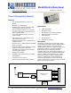
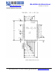
7. Antenna Design. The pattern from the rf_out terminal pad should be
designed with 50ohms impedance and traced with straight lines. (see
diagram to the right) The rf_out signal line should not run under of near the
RN21 module. The GND plane should be on the side of the PCB which the
module is mounted. The GND should be reinforced with through-hole
connections and other means to stabilize the electric potential.
8. Soldering Reflow Profile.
Lead-Free Solder Reflow
Temp: 230 degree C, 30-40 seconds, Peak 250 degree C maximum.
Preheat temp: 165 +- 15 degree C, 90 to 120 seconds.
Time: Single Pass, One Time
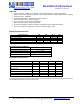
Compliance Information
Category
Country
Standard
Radio
USA
FCC Part 15 Subpart B: 2008 Class B
FCC CRF Title 47 Part 15 Subpart C
FCC ID:
T9J-RN42
EUROPE
ETSI EN 301 489-1 V1.8.1
ETSI EN 301 489-17 V2.1.1
ETSI EN 300 328 V1.7.1
CANADA
IC RSS-210 low power comm. device
Certification Number:
6514A-RN42
EMC
USA
FCC CFR47 Part 15 subclass B
EUROPE
EN 55022 Class B radiated
EN61000-4-2 ESD immunity
EN61000-4-3 radiated field
EN61000-4-6 RF immunity
EN61000-4-8 power magnetic immunity
Bluetooth
BQB LISTED
B014867- SPP and DUN profiles
Environmental
RoHS
RoHS compliant
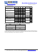
Ordering Information
Part Number
Description
RN-42
Standard Application firmware (SPP/DUN Master and Slave)
RN-42-H
HCI firmware (HCI over H4 UART)
RN-42-U
USB firmware (HCI over USB port, slave device at 12Mbps rate)
RN-42-N
No Antenna, Standard Application firmware (SPP/DUN Master and Slave)
For other configurations, contact Roving Networks directly.
Visit http://www.rovingnetworks.com/buynow.php for current pricing and a list of distributors carrying
our products.
RN21 Module
GND
RF_OUT
GND
RN21 Module
GND
RF_OUT
GND