
Data Sheet

MAX17043/MAX17044
Compact, Low-Cost 1S/2S Fuel Gauges
with Low-Battery Alert
_______________________________________________________________________________________ 9
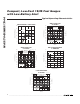
SLEEP (Sleep Bit)
Writing SLEEP to logic 1 forces the ICs into Sleep
mode. Writing SLEEP to logic 0 forces the ICs to exit
Sleep mode. The power-up default value for SLEEP is
logic 0.
X (Don't Care)
This bit reads as either a logic 0 or logic 1. This bit cannot
be written.
ALRT (ALERT Flag)
This bit is set by the IC when the SOC register value
falls below the alert threshold setting and an interrupt is
generated. This bit can only be cleared by software.
The power-up default value for ALRT is logic 0.
ATHD (Alert Threshold)
The alert threshold is a 5-bit value that sets the state of
charge level where an interrupt is generated on the
ALRT pin. The alert threshold has an LSb weight of 1%
and can be programmed from 1% up to 32%. The
threshold value is stored in two’s-complement form
(00000 = 32%, 00001 = 31%, 00010 = 30%, 11111 =
1%). The power-up default value for ATHD is 4% or 1Ch.
COMMAND Register
The COMMAND register allows the host processor to
send special commands to the IC. Valid COMMAND
register write values are listed as follows. All other
COMMAND register values are reserved. Table 3
shows COMMAND register commands.
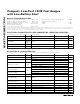
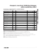
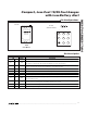
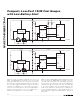
Application Examples
The MAX17043/MAX17044 have a variety of configura-
tions, depending on the application. Table 4 shows the
most common system configurations and the proper
pin connections for each.
VALUE COMMAND DESCRIPTION
5400h POR
See the Power-On Reset
(POR) section.
Table 3. COMMAND Register Commands
SYSTEM CONFIGURATION IC V
DD
ALRT QSTRT
1S Pack-Side Location MAX17043 Power directly from battery Leave unconnected Connect to GND
1S Host-Side Location MAX17043 Power directly from battery Leave unconnected Connect to GND
1S Host-Side Location,
Low Cell Interrupt
MAX17043 Power directly from battery
Connect to system
interrupt
Connect to GND
1S Host-Side Location,
Hardware Quick-Start
MAX17043 Power directly from battery Leave unconnected
Connect to rising-edge
reset signal
2S Pack-Side Location MAX17044
Power from +2.5V to +4.5V
LDO in pack
Leave unconnected Connect to GND
2S Host-Side Location MAX17044
Power from +2.5V to +4.5V
LDO or PMIC
Leave unconnected Connect to GND
2S Host-Side Location,
Low Cell Interrupt
MAX17044
Power from +2.5V to +4.5V
LDO or PMIC
Connect to system
interrupt
Connect to GND
2S Host-Side Location,
Hardware Quick-Start
MAX17044
Power from +2.5V to +4.5V
LDO or PMIC
Leave unconnected
Connect to rising-edge
reset signal
Table 4. Possible Application Configurations
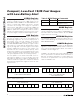
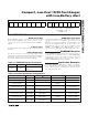
Figure 5. CONFIG Register Format
MSB—ADDRESS 0Ch LSB—ADDRESS 0Dh
R C OM P
2
7
R C OM P
2
6
R C OM P
2
5
R C OM P
2
4
R C OM P
2
3
R C OM P
2
2
R C OM P
2
1
R C OM P
2
0
SLEEP X ALRT
ATHD
2
4
ATHD
2
3
ATHD
2
2
ATHD
2
1
ATHD
2
0
MSB LSB MSB LSB
ATHD UNITS: 1 LSB = 2’S COMPLEMENT 1%
ATHD RANGE: 11111b = 1%
00000b = 32%