
Data Sheet

MAX17043/MAX17044
Compact, Low-Cost 1S/2S Fuel Gauges
with Low-Battery Alert
12 ______________________________________________________________________________________
Bus Timing
The MAX17043/MAX17044 are compatible with any bus
timing up to 400kHz. No special configuration is
required to operate at any speed.
2-Wire Command Protocols
The command protocols involve several transaction for-
mats. The simplest format consists of the master writing
the START bit, slave address, R/W bit, and then moni-
toring the acknowledge bit for presence of the
MAX17043/MAX17044. More complex formats, such as
the Write Data and Read Data, read data and execute
device-specific operations. All bytes in each command
format require the slave or host to return an acknowl-
edge bit before continuing with the next byte. Table 5
shows the key that applies to the transaction formats.
Basic Transaction Formats
A write transaction transfers 2 or more data bytes to the
MAX17043/MAX17044. The data transfer begins at the
memory address supplied in the MAddr byte. Control of
the SDA signal is retained by the master throughout the
transaction, except for the acknowledge cycles:
A read transaction transfers 2 or more bytes from the
MAX17043/MAX17044. Read transactions are com-
posed of two parts, a write portion followed by a read
portion, and are therefore inherently longer than a write
transaction. The write portion communicates the starting
point for the read operation. The read portion follows
immediately, beginning with a Repeated START, slave
address with R/W set to a 1. Control of SDA is assumed
by the MAX17043/MAX17044, beginning with the slave
address acknowledge cycle. Control of the SDA signal
is retained by the MAX17043/MAX17044 throughout the
transaction, except for the acknowledge cycles. The
master indicates the end of a read transaction by
responding to the last byte it requires with a no
acknowledge. This signals the MAX17043/MAX17044
that control of SDA is to remain with the master following
the acknowledge clock.
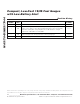
Write Data Protocol
The write data protocol is used to write to register to the
MAX17043/MAX17044 starting at memory address
MAddr. Data0 represents the data written to MAddr,
Data1 represents the data written to MAddr + 1, and
DataN represents the last data byte, written to MAddr +
N. The master indicates the end of a write transaction
by sending a STOP or Repeated START after receiving
the last acknowledge bit:
The MSB of the data to be stored at address MAddr
can be written immediately after the MAddr byte is
acknowledged. Because the address is automatically
incremented after the LSB of each byte is received by
the MAX17043/MAX17044, the MSB of the data at
address MAddr + 1 can be written immediately after
the acknowledgment of the data at address MAddr. If
the bus master continues an autoincremented write
transaction beyond address 4Fh, the MAX17043/
MAX17044 ignore the data. A valid write must include
both register bytes. Data is also ignored on writes to
read-only addresses. Incomplete bytes and bytes that
are not acknowledged by the MAX17043/MAX17044
are not written to memory.
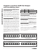
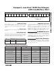
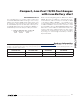
SAddr W. A. MAddr. A. Data0. A. Data1. A... DataN. A
Read: S. SAddr W. A. MAddr. A. Sr. SAddr R. A. Data0. A. Data1. N. P
Write Portion Read Portion
Write: S. SAddr W. A. MAddr. A. Data0. A. Data1. A. P
KEY DESCRIPTION KEY DESCRIPTION
S START bit Sr Repeated START
SAddr Slave address (7 bit) W R/W bit = 0
MAddr Memory address byte P STOP bit
Data Data byte written by master Data Data byte returned by slave
A Acknowledge bit—master A Acknowledge bit—slave
N No acknowledge—master N No acknowledge—slave
Table 5. 2-Wire Protocol Key