
Data Sheet

NAU7802 24-bit ADC
Nuvoton Confidential - 29 - Revision 1.7
11 DEVICE REGISTER MAP DETAILS
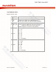
11.1 REG0x00:PU_CTRL
Register Default = 0x00
Bit
Name
Description
7
AVDDS
AVDD source select
1 = Internal LDO
0 = AVDD pin input (default)
6
OSCS
System clock source select
1 = External Crystal
0 = Internal RC oscillator (default)
5
CR
Cycle ready (Read only Status)
1 = ADC DATA is ready
4
CS
Cycle start
Synchronize conversion to the rising edge of this register
3
PUR
Power up ready (Read Only Status)
1 = Power Up ready
0 = Power down, not ready
2
PUA
Power up analog circuit
1 = Power up the chip analog circuits (PUD must be 1)
0 = Power down (default)
1
PUD
Power up digital circuit
1 = Power up the chip digital logic
0 = power down (default)
0
RR
Register reset
1 = Register Reset, reset all register except RR
0 = Normal Operation (default)
RR is a level trigger reset control. RR=1, enter reset state,
RR=0, leave reset state back to normal state.