
Data Sheet

NAU7802 24-bit ADC
Nuvoton Confidential - 16 - Revision 1.7
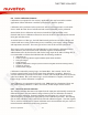
8.3.2 2-Wire Write Operation
A Write operation consists of a two-byte instruction followed by one or more Data Bytes. A Write
operation requires a START condition, followed by a valid device address byte with R/W=0, a valid
control address byte, data byte(s), and a STOP condition.
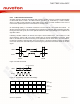
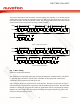
When more than one Data Byte is written, this is known as a "burst write" operation. In this operation,
the host may write sequential bytes of information simply by transmitting a new data byte after each
ACK from the NAU7802. The NAU7802 automatically increments the register address by one for each
subsequent byte-write operation. This will continue until the STOP condition is met.
The NAU87802 is permanently programmed with “010 1010” (0x2A) as the Device Address. If the
Device Address matches this value, the NAU7802 will respond with the expected ACK signaling as it
accepts the data being transmitted into it.
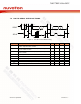
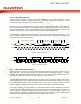
Device Address = 0101010
1 2
7
8 9
Device
ACK
4
3
6
5
0 1 0 1 0 1 0
0=W
START
9
8
A7
1
2 ...7
A0
9
8
D7
1
2 ...7
D0
STOP
A6...A1 D6...D1
Device
ACK
Device
ACK
Control (REG)
Address = A7..A0
DATA BYTE
= D7... D0
R/W
SCLK
SDIO
Figure 5: Single Write Sequence
ACK ACK
START STOP
Write REG Addr[7:0] ACK
Write Data[7:0] for
REG “Addr+1”
SCLK
SDIO
ACK
Write Data [7:0]
for REG “Addr”
1 2 ….. 7 8 9 1 2 ….. 8 9 1 2 ….. 8 9 1 2 ….. 8 9
Device Address[6:0]
= 0101010
Figure 6: Burst Write Sequence
8.3.3 2-Wire Single Read Operation
A Read operation consists of a three-byte Write instruction followed by a Read instruction of one or
more data bytes. The bus master initiates the operation issuing the following sequence: a START
condition, device address byte with the R/W bit set to “0”, and a Control Register Address byte. This
indicates to the slave device which of its control registers is to be accessed.
The NAU7802 is permanently programmed with “010 1010” (0x2A) as its device address. If the device
address matches this value, the NAU7802 will respond with the expected ACK signaling as it accepts
the Control Register Address being transmitted into it. After this, the master transmits a second
START condition, and a second instantiation of the same device address, but now with R/W=1.
After again recognizing its device address, the NAU7802 transmits an ACK, followed by a one byte
value containing the data from the selected control register inside the NAU7802. During this phase, the
master generates the ACK signaling with each byte transferred from the NAU7802. If there is no
STOP signal from the master, the NAU7802 will internally auto-increment the target Control Register
Address and then output the data bytes for this next register in the sequence.