
Data Sheet

NAU7802 24-bit ADC
Nuvoton Confidential - 13 - Revision 1.7
8 FUNCTIONAL DESCRIPTION
8.1 Analog input (VIN1P, VIN1N, VIN2N, VIN2P)
The input signal to be measured is applied to one of two differential input signal pairs. The desired
signal pair is selected using an analog input multiplexer, which is controlled by settings in the device
command and control registers. The 8-pin version of the device supports only one input signal pair.
This device is optimized to accept differential input signals, but can also measure single-ended signals.
When measuring single-ended signals with respect to ground, connect the negative input (VIN1N or
VIN2N) to ground and connect the input signal to the positive input (VIN1P or VIN2P). Note that when
this device is configured this way, only half of the converter full-scale range is used, since only positive
digital output codes are produced.
8.2 Power supply
The digital power supply DVDD should use the same power source as used for the host processor
supporting the digital interface communication. The analog power supply AVDD can be provided by
external regulator output (power-on default setting) or provided by a built-in voltage regulator. The eight
programmable output voltage levels of the built-in regulator are: off (high-Z output, default power-on
setting), 2.4V, 2.7V, 3.0V 3.3V, 3.6V, 4.2V, and 4.5V. This output is intended to provide the driving
current for external sensors such as load cells for weight measurement applications.
8.3 2-Wire-Serial Control and Data Bus (I
2
C Style Interface)
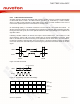
The serial interface provides a 2-wire bidirectional read/write data interface similar to and typically
compatible with standard I2C protocol. This protocol defines any device that sends CLK onto the bus
as a master, and the receiving device as slave. The NAU7802 can function only as a slave device.
An external clock drives the device, and in accordance with the protocol, data is sent to or from the
device accordingly. All functions are controlled by means of a register control interface in the device.
Additionally, a "data ready" output pin is provided to indicate to the host that a new conversion has
been completed and that data are ready to be read from the device. The host may either use this
signal or poll device register R0x00 Bit 5 to determine when new data are available.