
Data Sheet

Page 28 ams Datasheet
Document Feedback [v1-04] 2018-Jul-09
AS7265x − Detailed Description
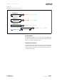
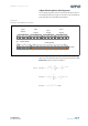
I²C Virtual Register Set
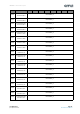
The figure below provides a summary of the AS72651 I²C regis-
ter set for the AS72651 which serves as the master interface of
the 3 device AS7265x set. Figures after that provide additional
register details. All register data is hex, and all multi-byte enti-
ties are Big Endian (most significant byte is situated at the low-
est register address).
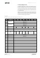
Multiple byte registers (2 byte integer, or, 4 byte floating point)
must be read in the order of ascending register addresses (low
to high) and if capable of being written to, must also be written
in the order ascending register addresses.
Figure 26:
AS72651 I²C Master Device Virtual Register Set Overview
Addr Name <D7> <D6> <D5> <D4> <D3> <D2> <D1> <D0>
0x00
HW Version
HW Version H
0x01 HW Version L
0x02
FW Version
FW Version H
0x03 FW Version L
0x04 Configuration SRST INT GAIN BANK DATA_RDY FRST
0x05 Integration Time Integration Time
0x06 Temperature Temperature
0x07
LED
Configuration
READ_
ERR
LED_
DRV
ENA-
BLELED
_DRV
LED_INT
ENABL
E LED_
INT
0x08 RAW value R, G, A RAW value H
0x09 RAW value R, G, A RAW value L
0x0A RAW value S, H, B RAW value H
0x0B RAW value S, H, B RAW value L
0x0C RAW value T, I, C RAW value H
0x0D RAW value T, I, C RAW value L
0x0E RAW value U, J, D RAW value H
0x0F RAW value U, J, D RAW value L
0x10 RAW value V, K, E RAW value H
0x11 RAW value V, K, E RAW value L
0x12 RAW value W, L, F RAW value H
0x13 RAW value W, L, F RAW value L