
Data Sheet
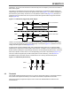
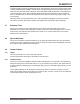
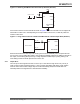
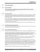
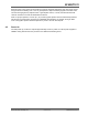
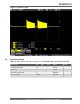
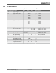

Figure 3-6. Obtaining HeartBeat Pulses with a Pull-up Resistor (SOT23-6)
OUT
VDD
SNSK
SNS
SYNC/MODE
VSS
2
6
4
3
1
5
VDD
Ro
HeartBeat" Pulse
If the sensor is wired to a microcontroller as shown in Figure 3-7, the microcontroller can reconfigure the
load resistor to either Vss or Vdd depending on the output state of the QT1011, so that the pulses are
evident in either state.
Figure 3-7. Using a Microcontroller to Obtain HeartBeat Pulses in Either Output State (SOT23-6)
OUT
SNSK
SNS
SYNC/MODE
6
4
3
1
Ro
Microcontroller
Port_M.x
Port_M.y
Electromechanical devices like relays will usually ignore the short HeartBeat pulse. The pulse also has
too low a duty cycle to visibly affect LEDs. It can be filtered completely if desired, by adding an RC filter to
the output, or if interfacing directly and only to a high-impedance CMOS input, by doing nothing or at
most adding a small noncritical capacitor from OUT to Vss.
3.9.3 Output Drive
The OUT pin is active high and can sink or source up to 2 mA. When a large value of Cs (>20 nF) is
used, the OUT current should be limited to <1 mA to prevent gain-shifting side effects, which happen
when the load current creates voltage drops on the die and bonding wires; these small shifts can
materially influence the signal level to cause detection instability.
AT42QT1011
© 2017 Microchip Technology Inc.
Datasheet
DS40001947A-page 14