AT42QT1011 AT42QT1011 Data Sheet Introduction The AT42QT1011 is a digital burst mode charge-transfer sensor that is capable of detecting near proximity or touch, making it ideal for implementing touch controls. The QT1011 is designed specifically for human interfaces like control panels, appliances, toys, lighting controls, or anywhere a mechanical switch or button may be found.
AT42QT1011 • • • – 1.8 V – 5.5 V; 17 µA at 1.
Table of Contents Introduction......................................................................................................................1 Features.......................................................................................................................... 1 1. Pinout and Schematic................................................................................................5 1.1. 1.2. 1.3. Pinout Configurations.......................................................................
AT42QT1011 7. Revision History.......................................................................................................26 The Microchip Web Site................................................................................................ 27 Customer Change Notification Service..........................................................................27 Customer Support.........................................................................................................
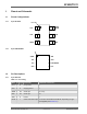
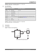
AT42QT1011 1. Pinout and Schematic 1.1 Pinout Configurations 1.1.1 6-pin SOT23-6 Pin 1 ID 1.1.2 OUT 1 6 SYNC/ MODE VSS 2 5 VDD SNSK 3 4 SNS 8-pin UDFN/USON Pin 1 ID 1.2 Pin Descriptions 1.2.1 6-pin SOT23-6 Table 1-1. Pin Listing SNSK 1 8 SNS N/C 2 7 VDD N/C 3 6 SYNC/MODE VSS 4 5 OUT Name Pin Type Comments If Unused, Connect To...
AT42QT1011 Legend: I = Input only, O = Output only, push-pull, I/O = Input/output, OD = Open drain output, P = Ground or power 1.2.2 8-pin UDFN/USON Table 1-2. Pin Listing Name Pin Type Comments If Unused, Connect To... SNSK 1 I/O Sense pin Cs + Key N/C 2 — No connection — N/C 3 — No connection — VSS 4 P Supply ground — OUT 5 O Output state — SYNC/ 6 MODE I SYNC and Mode Input Pin is either SYNC/Slow/Fast Mode, depending on logic level applied (see Section 3.
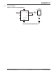
AT42QT1011 1.3.2 8-pin UDFN/USON Figure 1-2. Basic Circuit Configuration Vdd SENSE ELECTRODE 7 VDD 5 2 3 SNSK OUT NC SNS NC SYNC/MODE Rs 1 Cs 8 6 Cx VSS 4 Note: A bypass capacitor should be tightly wired between Vdd and Vss and kept close to pin 5. © 2017 Microchip Technology Inc.
AT42QT1011 2. Overview of the AT42QT1011 2.1 Introduction The AT42QT1011 is a digital burst mode charge-transfer sensor that is capable of detecting nearproximity or touch, making it ideal for implementing touch controls. With the proper electrode and circuit design, the self-contained digital IC will project a touch or proximity field to several centimeters through any dielectric like glass, plastic, stone, ceramic, and even most kinds of wood.
AT42QT1011 and composition of any overlaying panel material, and the degree of ground coupling of both sensor and object. 2.4.2 Increasing Sensitivity In some cases it may be desirable to increase sensitivity; for example, when using the sensor with very thick panels having a low dielectric constant, or when the device is used as a proximity sensor. Sensitivity can often be increased by using a larger electrode or reducing panel thickness.
AT42QT1011 3. Operation Specifics 3.1 Run Modes 3.1.1 Introduction The QT1011 has three running modes which depend on the state of the SYNC pin (high or low). 3.1.2 Fast Mode The QT1011 runs in Fast mode if the SYNC pin is permanently high. In this mode the QT1011 runs at maximum speed at the expense of increased current consumption. Fast mode is useful when speed of response is the prime design requirement.
AT42QT1011 interference, or it can be used to enhance noise immunity from low frequency sources such as 50Hz or 60Hz mains signals. The SYNC pin is sampled at the end of each burst. If the device is in Fast mode and the SYNC pin is sampled high, then the device continues to operate in Fast mode (Figure 3-1). If SYNC is sampled low, then the device goes to sleep. From then on, it will operate in SYNC mode (Figure 3-2).
AT42QT1011 3.3 Max On-duration The max on-duration of this device is infinite; that is, the device will not automatically recalibrate due to a persistent detection. 3.4 Detect Integrator It is desirable to suppress detections generated by electrical noise or from quick brushes with an object. To accomplish this, the QT1011 incorporates a Detect Integration (DI) counter that increments with each detection until a limit is reached, after which the output is activated.
AT42QT1011 increasing signals. Increasing signals should not be compensated for quickly, since an approaching finger could be compensated for partially or entirely before even approaching the sense electrode. However, an obstruction over the sense pad, for which the sensor has already made full allowance, could suddenly be removed leaving the sensor with an artificially elevated reference level and thus become insensitive to touch.
AT42QT1011 Figure 3-6. Obtaining HeartBeat Pulses with a Pull-up Resistor (SOT23-6) VDD 5 HeartBeat" Pulse VDD Ro 1 OUT SNSK SNS 3 4 SYNC/MODE 6 VSS 2 If the sensor is wired to a microcontroller as shown in Figure 3-7, the microcontroller can reconfigure the load resistor to either Vss or Vdd depending on the output state of the QT1011, so that the pulses are evident in either state. Figure 3-7. Using a Microcontroller to Obtain HeartBeat Pulses in Either Output State (SOT23-6) Port_M.
AT42QT1011 4. Circuit Guidelines 4.1 More Information ® Refer to Application Note QTAN0002, "Secrets of a Successful QTouch Design", and the "Touch Sensors Design Guide" (both downloadable from http://www.microchip.com), for more information on construction and design methods. 4.2 Sample Capacitor Cs is the charge sensing sample capacitor. The required Cs value depends on the thickness of the panel and its dielectric constant. Thicker panels require larger values of Cs.
AT42QT1011 Electrode trace routing: Keep the electrode trace (and the electrode itself) away from other signal, power, and ground traces including over or next to ground planes. Adjacent switching signals can induce noise onto the sensing signal; any adjacent trace or ground plane next to, or under, the electrode trace will cause an increase in Cx load and desensitize the device. Note: For proper operation, a 100 nF (0.
AT42QT1011 5. Specifications 5.1 Absolute Maximum Specifications Operating temperature –40°C to +85°C Storage temperature –55°C to +125°C Vdd 0 to +6.5 V Max continuous pin current, any control or drive pin ±20 mA Short circuit duration to Vss, any pin Infinite Short circuit duration to Vdd, any pin Infinite Voltage forced onto any pin –0.6V to (Vdd + 0.6) V CAUTION: Stresses beyond those listed under Absolute Maximum Specifications may cause permanent damage to the device.
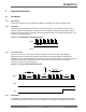
AT42QT1011 Parameter Description Min Typ Max Units Notes Tg2 Time between end of burst and start of the next (LP mode) – 80 – ms Increases with decreasing Vdd See Figure 5-1 Tbl Burst length – 2.45 – ms Vdd, Cs and Cx dependent. See Section 4.2 for capacitor selection. Tr Response time – – 100 ms Thb HeartBeat pulse width – 15 – μs Figure 5-1. Tg2 Time Between Bursts (LP Mode) © 2017 Microchip Technology Inc.
AT42QT1011 Figure 5-2. Tbl Burst Length 5.4 Signal Processing Table 5-2. Vdd = 3.0V, Cs = 4.7 nF, Cx = 5 pF, Ta = recommended range, unless otherwise noted Description Min Threshold differential 10 counts Hysteresis 2 counts Consensus filter length 4 samples Max on-duration Infinite seconds © 2017 Microchip Technology Inc.
AT42QT1011 5.5 DC Specifications Table 5-3. Vdd = 3.0V, Cs = 4.7 nF, Cx = 5 pF, Ta = recommended range, unless otherwise noted Parameter Description Min Vdd Supply voltage 1.8 Idd Supply current, Fast mode – IddI Typ Max Units Notes 5.5 V 203.0 – 246.0 378.5 542.5 729.0 μA 1.8 V 2.0 V 3.0 V 4.0 V 5.0 V Supply current, LP mode – 16.5 19.5 34.0 51.5 73.5 – μA 1.8 V 2.0 V 3.0 V 4.0 V 5.
AT42QT1011 5.6 Mechanical Dimensions 5.6.1 6-pin SOT23-6 D 5 6 E E1 A 4 A2 Pin #1 ID 1 b 0.10 C SEATING PLANE A 3 2 A A1 C Side View e Top View A2 A 0.10 C SEATING PLANE c 0.25 O L C View A-A SEATING PLANE C A1 SEE VIEW B View B COMMON DIMENSIONS (Unit of Measure = mm) Notes: 1. This package is compliant with JEDEC specification MO-178 Variation AB. 2. Dimension D does not include mold Flash, protrusions or gate burrs.
AT42QT1011 5.6.2 8-pin UDFN/USON Top view 8 7 6 Side view Bottom view A D2 e 5 5 8 k E C0.2 E2 PIN 1 ID L 1 2 3 4 4 D 0.05 C f A 8X d 1 b A1 0.05 C C Side view COMMON DIMENSIONS (Unit of Measure = mm) A1 MIN NOM MAX A - - 0.60 A1 0.00 - 0.05 b 0.20 - 0.30 D 1.95 2.00 2.05 D2 1.40 1.50 1.60 1.95 2.00 0.90 1.00 SYMBOL NOTES: 1. All dimensions are in mm. Angles in degrees. 2. Coplanarity applies to the exposed pad as well as the terminals.
AT42QT1011 5.7 Part Marking 5.7.1 AT42QT1011– 6-pin SOT23-6 Pin 1 ID 1011 Abbreviated Part Number: AT42QT1011 Note: Samples of the AT42QT1011 may also be marked T10E. 5.7.
AT42QT1011 5.9 Moisture Sensitivity Level (MSL) MSL Rating Peak Body Temperature Specifications MSL1 260oC IPC/JEDEC J-STD-020 © 2017 Microchip Technology Inc.
AT42QT1011 6. Associated Documents For additional information, refer to the following document (downloadable from the Touch Technology area of the Microchip website, www.microchip.com): • • Touch Sensors Design Guide ® QTAN0002 – Secrets of a Successful QTouch Design © 2017 Microchip Technology Inc.
AT42QT1011 7. Revision History Revision No. History Revision A – May 2009 Initial release Revision B – August 2009 Update for chip revision 2.2 Revision C – August 2009 Minor update for clarity Revision D – January 2010 Power specifications updated for revision 2.4.1 Revision E – January 2010 Part markings updated Revision F – February 2010 MSL specification revised Other minor updates Revision G – March 2010 Update for chip revision 2.
AT42QT1011 The Microchip Web Site Microchip provides online support via our web site at http://www.microchip.com/. This web site is used as a means to make files and information easily available to customers.
AT42QT1011 • Neither Microchip nor any other semiconductor manufacturer can guarantee the security of their code. Code protection does not mean that we are guaranteeing the product as “unbreakable.” Code protection is constantly evolving. We at Microchip are committed to continuously improving the code protection features of our products. Attempts to break Microchip’s code protection feature may be a violation of the Digital Millennium Copyright Act.
AT42QT1011 ISBN: 978-1-5224-2070-5 Quality Management System Certified by DNV ISO/TS 16949 Microchip received ISO/TS-16949:2009 certification for its worldwide headquarters, design and wafer fabrication facilities in Chandler and Tempe, Arizona; Gresham, Oregon and design centers in California ® ® and India. The Company’s quality system processes and procedures are for its PIC MCUs and dsPIC ® DSCs, KEELOQ code hopping devices, Serial EEPROMs, microperipherals, nonvolatile memory and analog products.
Worldwide Sales and Service AMERICAS ASIA/PACIFIC ASIA/PACIFIC EUROPE Corporate Office 2355 West Chandler Blvd. Chandler, AZ 85224-6199 Tel: 480-792-7200 Fax: 480-792-7277 Technical Support: http://www.microchip.com/ support Web Address: www.microchip.