
Data Sheet


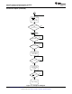


4ms/div
500mV/div
USB5 CurrentLimit00
200mA/div
200mA/div
200mA/div
I
OUT
I
IN
V
IN
(5V)
I
BAT
Inputcollapses
Inputcurrentlimitis
reducedtoprevent
crashingthesupply
InputregulatedtoV
IN_DPM
bq24072
,
bq24073
,
bq24074
,
bq24075
,
bq24079
SLUS810K –SEPTEMBER 2008–REVISED MARCH 2015
www.ti.com
Feature Description (continued)
When the IN source is connected, priority is given to the system load. The DPPM and Battery Supplement
modes are used to maintain the system load. Figure 19 and Figure 20 illustrate examples of the DPPM and
supplement modes. These modes are explained in detail in the following sections.
9.3.4.1.1 Input DPM Mode (V
IN
-DPM)
The bq2407x utilizes the V
IN
-DPM mode for operation from current-limited USB ports. When EN1 and EN2 are
configured for USB100 (EN2=0, EN1=0) or USB500 (EN2=0, EN2=1) modes, the input voltage is monitored. If
V
IN
falls to V
IN-DPM
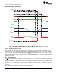
, the input current limit is reduced to prevent the input voltage from falling further. This prevents
the bq2407x from crashing poorly designed or incorrectly configured USB sources. Figure 18 shows the V
IN
-DPM
behavior to a current limited source. In this figure, the input source has a 400-mA current limit and the device is
in USB500 mode (EN1=1, EN2=0).
Figure 18. V
IN
-DPM Waveform
9.3.4.1.2 DPPM Mode
When the sum of the charging and system load currents exceeds the maximum input current (programmed with
EN1, EN2, and ILIM pins), the voltage at OUT decreases. Once the voltage on the OUT pin falls to V
DPPM
, the
bq2407x enters DPPM mode. In this mode, the charging current is reduced as the OUT current increases in
order to maintain the system output. Battery termination is disabled while in DPPM mode.
9.3.4.1.3 Battery Supplement Mode
While in DPPM mode, if the charging current falls to zero and the system load current increases beyond the
programmed input current limit, the voltage at OUT reduces further. When the OUT voltage drops below the
V
BSUP1
threshold, the battery supplements the system load. The battery stops supplementing the system load
when the voltage at OUT rises above the V
BSUP2
threshold.
During supplement mode, the battery supplement current is not regulated (BAT-FET is fully on), however there is
a short circuit protection circuit built in. Figure 35 demonstrates supplement mode. If during battery supplement
mode, the voltage at OUT drops V
O(SC2)
below the BAT voltage, the OUT output is turned off if the overload
exists after t
DGL(SC2)
. The short circuit recovery timer then starts counting. After t
REC(SC2)
, OUT turns on and
attempts to restart. If the short circuit remains, OUT is turned off and the counter restarts. Battery termination is
disabled while in supplement mode.
18 Submit Documentation Feedback Copyright © 2008–2015, Texas Instruments Incorporated
Product Folder Links: bq24072 bq24073 bq24074 bq24075 bq24079