
Data Sheet

NEO-M8P - Data Sheet
UBX-15016656 - R06 Early Production Information Functional description
Page 9 of 30
accuracy of the Base station position must be optimized. In the UBX-NAV-RELPOSNED message, the relative
position is described in the form of an NED vector.
The absolute accuracy of the Base station position will be transferred to the absolute accuracy of a Rover
operating in differential mode. The NEO-M8P-2 Base station module comes with functionalities to ensure the
best possible absolute accuracy as described in section 1.6.2.
1.6.2 Base station mode (NEO-M8P-2)
The NEO-M8P-2 can be set-up to operate either as a static or as a mobile base station using the appropriate
configuration messages. Prior to use, the NEO-M8P-2 must be configured to produce the required RTCM
messages using UBX-CFG-MSG. For static operation the user has a choice of providing a set of position
coordinates explicitly or by commanding the receiver to produce its own via a self survey-in function. When
either mode is set correctly with a valid position, RTCM reference position messages will be enabled for
transmission. When setting for a moving base station mode the base receiver must ensure that the fixed location
mode is disabled and the reference transmits the RTCM 4072 message.
1.6.2.1 Static mode
The NEO-M8P-2 can be set to use previously surveyed coordinates of the Base antenna position. Assuming such
coordinates are of highest quality, this method ensures the best absolute accuracy for the Rover units. The device
will output RTCM 3 messages when successfully configured in this mode.
This mode is set by using the command UBX-CFG-TMODE3 with receiver mode flag “Fixed Mode”. The input
WGS84 coordinates can be given in LAT/LON/ALT or ECEF format. Once set, the base station will monitor its
position in order to detect any position change from its designated position. Position changes larger than 100 m
are reported via a warning message.
The NEO-M8P-2 is capable to self survey-in its coordinates in situations where the Base antenna is not surveyed
using other means. When this mode is employed the user provides constraints on accuracy and a minimum
observation time. The receiver will average its position estimates and output any configured RTCM 3 observation
messages until both constraints are met. After this, it will begin operating in static mode and will output a
configured RTCM 3 reference station message.
This mode is set by using the command UBX-CFG-TMODE3 with the mode flag “Survey In” set. The input
WGS84 coordinates can be given in LAT/LON/ALT or ECEF format.
1.6.2.2 Moving Baseline mode
The moving baseline (MB) mode differs from the standard RTK operation in that the base station is no longer
stationary at a pre-determined location. Both the reference station and rover receivers are allowed to move
while computing an accurate vector between the receiver's antennae. To ensure operation in this mode, use the
message UBX-CFG-TMODE3 with the mode flag “disabled” set, and ensure that the RTCM 4072 message has
been enabled.
This mode enables the calculation of heading on dynamic or static platforms, plus provides a centimeter level
accurate 3D vector for use in dynamic positioning examples, e.g. a UAV ”follow me” feature.
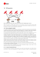
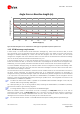
1.6.2.3 Attitude Sensing
Using the moving baseline functionality with fixed base and rover antenna positions on a platform gives the
means to estimate the baseline angle with respect to the local datum via the relative position information. This
derived angular error will then be proportional to the baseline length. Figure 3 below provides the trend for
baseline lengths up to 1 m for a typical (1 sigma) relative position error of 0.8 cm.
When using similar low cost patch antennas it is best to match their orientation to ensure the best error
estimate.