
Data Sheet

NEO-M8P - Data Sheet
UBX-15016656 - R06 Early Production Information Electrical specification
Page 20 of 30
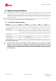
4.2 Operating conditions
All specifications are at an ambient temperature of 25°C. Extreme operating temperatures can significantly
impact specification values. Applications operating near the temperature limits should be tested to ensure
the specification.
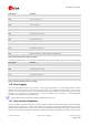
Parameter Symbol Min Typical Max Units Condition
Power supply voltage VCC 2.7 3.0 3.6 V
Supply voltage USB VDD_USB 3.0 3.3 3.6 V
Backup battery voltage V_BCKP 1.4 3.6 V
Backup battery current I_BCKP 15 µA V_BCKP = 1.8 V,
VCC = 0 V
SW backup current I_SWBCKP 30 µA VCC = 3 V
Input pin voltage range Vin 0 VCC V
Digital IO Pin Low level input voltage Vil 0 0.2*VCC V
Digital IO Pin High level input voltage Vih 0.7*VCC VCC V
Digital IO Pin Low level output voltage Vol 0.4 V Iol = 4 mA
Digital IO Pin High level output
voltage
Voh VCC–0.4 V Ioh = 4 mA
Pull-up resistor for RESET_N Rpu 11
k
Ω
USB_DM, USB_DP VinU Compatible with USB with 27
Ω
series resistance
VCC_RF voltage VCC_RF VCC–0.1 V
VCC_RF output current ICC_RF 50 mA
Receiver Chain Noise Figure
12
NFtot 3 dB
Operating temperature Topr
–40 85 °C
Table 10: Operating conditions
Operation beyond the specified operating conditions can affect device reliability.
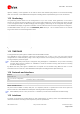
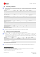
4.3 Indicative current requirements
Table 11 lists examples of the total system supply current for a possible application.
Values in Table 11 are provided for customer information only as an example of typical power
requirements. Values are characterized on samples, actual power requirements can vary depending on
firmware version used, external circuitry, number of satellites tracked, signal strength, type of start as well
as time, duration and conditions of test.
Parameter Symbol
Typ
GPS & GLONASS
Typ
GPS
Max Units Condition
Max. supply current
13
Iccp 67 mA
Average supply current
14, 15
Icc Acquisition
16
35 27 mA Estimated at 3 V
Icc Tracking
(Continuous mode)
33 25
mA Estimated at 3 V
Table 11: Indicative power requirements at 3.0 V
For more information about power requirements, see the NEO-M8P Hardware Integration Manual [1].
12
Only valid for the GPS band
13
Use this figure to dimension maximum current capability of power supply. Measurement of this parameter with 1 Hz bandwidth.
14
Use this figure to determine required battery capacity.
15
Simulated GNSS constellation using power levels of -130 dBm. VCC = 3.0 V
16
Average current from start-up until the first fix.