
Data Sheet

NEO-M8P - Data Sheet
UBX-15016656 - R06 Early Production Information Electrical specification
Page 19 of 30
4 Electrical specification
The limiting values given are in accordance with the Absolute Maximum Rating System (IEC 134). Stress
above one or more of the limiting values may cause permanent damage to the device. These are stress
ratings only and operation of the device at these or at any other conditions above those given in the
characteristics sections of the specification is not implied. Exposure to these limits for extended periods may
affect device reliability.
Where application information is given, it is advisory only and does not form part of the specification. For
more information see the NEO-M8P Hardware Integration Manual [1].
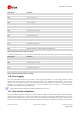
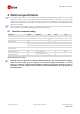
4.1 Absolute maximum rating
Parameter Symbol Condition Min Max Units
Power supply voltage VCC –0.5 3.6 V
Backup battery voltage V_BCKP –0.5 3.6 V
USB supply voltage VDD_USB
–0.5
3.6 V
Input pin voltage Vin –0.5 3.6 V
Vin_usb –0.5 VDD_USB V
Vrfin 0 6 V
DC current trough any digital I/O pin
(except supplies)
Ipin 10 mA
VCC_RF output current ICC_RF 100 mA
Input power at RF_IN Prfin source impedance =
50 Ω, continuous wave
15 dBm
Storage temperature Tstg
–40 85 °C
Table 9: Absolute maximum ratings
Stressing the device beyond the “Absolute Maximum Ratings” may cause permanent damage.
These are stress ratings only. The product is not protected against overvoltage or reversed
voltages. If necessary, voltage spikes exceeding the power supply voltage specification, given in
table above, must be limited to values within the specified boundaries by using appropriate
protection diodes.