
Data Sheet

NEO-M8P - Data Sheet
UBX-15016656 - R06 Early Production Information Pin definition
Page 16 of 30
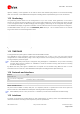
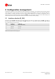
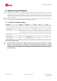
2 Pin definition
2.1 Pin assignment
Figure 5: Pin Assignment
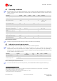
Table 6: Pinout
Pins designated Reserved should not be used. For more information about Pinouts see the NEO-M8P
Hardware Integration Manual [1].
No Name I/O Description
1 SAFEBOOT_N I SAFEBOOT_N (for future service, updates and reconfiguration, leave OPEN)
2 D_SEL I Interface select
3 TIMEPULSE O Time pulse (1PPS)
4 EXTINT I External Interrupt Pin
5 USB_DM I/O USB Data
6 USB_DP I/O USB Data
7 VDD_USB I USB Supply
8 RESET_N I RESET_N
9 VCC_RF O Output Voltage RF section
10 GND I Ground
11 RF_IN I GNSS signal input
12 GND I Ground
13 GND I Ground
14 LNA_EN O Antenna / External LNA power control
15 RTK_STAT O RTK status 0 – Fixed, blinking – receiving RTCM data, 1 – no corrections
16 GEOFENCE_STAT O Geofence status, user defined
17 Reserved - Reserved
18
SDA /
SPI CS_N
I/O
DDC Data if D_SEL =1 (or open)
SPI Chip Select if D_SEL = 0
19
SCL /
SPI CLK
I/O
DDC Clock if D_SEL =1(or open)
SPI Clock if D_SEL = 0
20
TxD /
SPI MISO
O
Serial Port if D_SEL =1(or open)
SPI MISO if D_SEL = 0
21
RxD /
SPI MOSI
I
Serial Port if D_SEL =1(or open)
SPI MOSI if D_SEL = 0
22 V_BCKP I Backup voltage supply
23 VCC I Supply voltage
24 GND I Ground