
Data Sheet
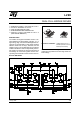
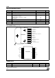
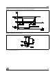
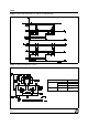

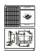

Figure 7 : For higher currents, outputs can be paralleled. Take care to parallel channel 1 with channel 4
and channel 2 with channel 3.
APPLICATION INFORMATION (Refer to the block diagram)
1.1. POWER OUTPUT STAGE
The L298 integrates two power output stages (A ; B).
The power output stage is a bridge configuration
and its outputs can drive an inductive load in com-
mon or differenzial mode, depending on the state of
the inputs. The current that flows through the load
comes out from the bridge at the sense output : an
external resistor (R
SA
; R
SB
.) allows to detect the in-
tensity of this current.
1.2. INPUT STAGE
Each bridge is driven by means of four gates the in-
put of which are In1 ; In2 ; EnA and In3 ; In4 ; EnB.
The In inputs set the bridge state when The En input
is high ; a low state of the En input inhibits the bridge.
All the inputs are TTL compatible.
2. SUGGESTIONS
A non inductive capacitor, usually of 100 nF, must
be foreseen between both Vs and Vss, to ground,
as near as possible to GND pin. When the large ca-
pacitor of the power supply is too far from the IC, a
second smaller one must be foreseen near the
L298.
The sense resistor, not of a wire wound type, must
be grounded near the negative pole of Vs that must
be near the GND pin of the I.C.
Each input must be connected to the source of the
driving signals by means of a very short path.
Turn-On and Turn-Off : Before to Turn-ON the Sup-
ply Voltage and before to Turn it OFF, the Enable in-
put must be driven to the Low state.
3. APPLICATIONS
Fig 6 shows a bidirectional DC motor control Sche-
matic Diagram for which only one bridge is needed.
The external bridge of diodes D1 to D4 is made by
four fast recovery elements (trr ≤ 200 nsec) that
must be chosen of a VF as low as possible at the
worst case of the load current.
The sense output voltage can be used to control the
current amplitude by chopping the inputs, or to pro-
vide overcurrent protection by switching low the en-
able input.
The brake function (Fast motor stop) requires that
the Absolute Maximum Rating of 2 Amps must
never be overcome.
When the repetitive peak current needed from the
load is higher than 2 Amps, a paralleled configura-
tion can be chosen (See Fig.7).
An external bridge of diodes are required when in-
ductive loads are driven and when the inputs of the
IC are chopped ; Shottky diodes would be preferred.
L298
7/13