
Data Sheet
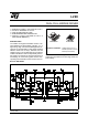
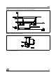
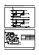
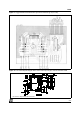

PIN CONNECTIONS (top view)
GND
Input 2
VSS
N.C.
Out 1
V
S
Out 2
Input 1
Enable A
Sense A
GND 10
8
9
7
6
5
4
3
2
13
14
15
16
17
19
18
20
12
1
11
GND
D95IN239
Input 3
Enable B
Out 3
Input 4
Out 4
N.C.
Sense B
GND
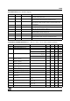
ABSOLUTE MAXIMUM RATINGS
Symbol Parameter Value Unit
V
S
Power Supply 50 V
V
SS
Logic Supply Voltage 7 V
V
I
,V
en
Input and Enable Voltage –0.3 to 7 V
I
O
Peak Output Current (each Channel)
– Non Repetitive (t = 100
µ
s)
–Repetitive (80% on –20% off; t
on
= 10ms)
–DC Operation
3
2.5
2
A
A
A
V
sens
Sensing Voltage –1 to 2.3 V
P
tot
Total Power Dissipation (T
case
= 75
°
C)
25 W
T
op
Junction Operating Temperature –25 to 130
°
C
T
stg
, T
j
Storage and Junction Temperature –40 to 150
°
C
THERMAL DATA
Symbol Parameter PowerSO20 Multiwatt15 Unit
R
th j-case
Thermal Resistance Junction-case Max. – 3
°
C/W
R
th j-amb
Thermal Resistance Junction-ambient Max. 13 (*) 35
°
C/W
(*) Mounted on aluminum substrate
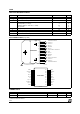
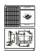
1
2
3
4
5
6
7
9
10
11
8
ENABLE B
INPUT 3
LOGIC SUPPLY VOLTAGE V
SS
GND
INPUT 2
ENABLE A
INPUT 1
SUPPLY VOLTAGE V
S
OUTPUT 2
OUTPUT 1
CURRENT SENSING A
TAB CONNECTED TO PIN 8
13
14
15
12
CURRENT SENSING B
OUTPUT 4
OUTPUT 3
INPUT 4
D95IN240A
Multiwatt15
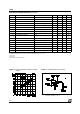
PowerSO20
L298
2/13