
Data Sheet

Page 69
RFM69HCW
Tel: + 86-755-82973805 Fax: +86- 755-82973550 E-mail: sales@hoperf.com http:/ / www.hoperf.com
ADVANCED COMMUNICATIONS & SENSING DATASHEET
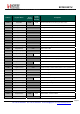
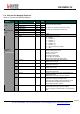
6.5. IRQ and Pin Mapping Registers
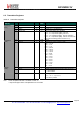
Table 27 IRQ and Pin Mapping Registers
Name
(Address)
Bits Variable Name Mode
Default
Value
Description
7-6 Dio0Mapping rw 00
5-4 Dio1Mapping rw 00
3-2 Dio2Mapping rw 00
RegDioMapping1
(0x25)
1-0 Dio3Mapping rw 00
7-6 Dio4Mapping rw 00
5-4 Dio5Mapping rw 00
Mapping of pins DIO0 to DIO5
See Table 21 for mapping in Continuous mode
See Table 22 for mapping in Packet mode
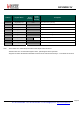
3 - r 0 unused
RegDioMapping2
(0x26)
2-0 ClkOut rw 111
*
Selects CLKOUT frequency:
000 → FXOSC
001 → FXOSC / 2
010 → FXOSC / 4
011 → FXOSC / 8
100 → FXOSC / 16
101 → FXOSC / 32
110 → RC (automatically enabled)
111 → OFF
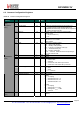
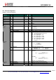
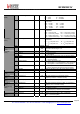
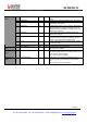
7 ModeReady r 1 Set when the operation mode requested in Mode, is ready
- Sleep: Entering Sleep mode
- Standby: XO is running
- FS: PLL is locked
- Rx: RSSI sampling starts
- Tx: PA ramp-up completed
Cleared when changing operating mode.
6 RxReady r 0 Set in Rx mode, after RSSI, AGC and AFC.
Cleared when leaving Rx.
5 TxReady r 0 Set in Tx mode, after PA ramp-up.
Cleared when leaving Tx.
4 PllLock r 0 Set (in FS, Rx or Tx) when the PLL is locked.
Cleared when it is not.
3 Rssi rwc 0 Set in Rx when the RssiValue exceeds RssiThreshold.
Cleared when leaving Rx.
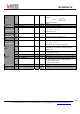
2 Timeout r 0 Set when a timeout occurs (see TimeoutRxStart and
TimeoutRssiThresh)
Cleared when leaving Rx or FIFO is emptied.
1 AutoMode r 0 Set when entering Intermediate mode.
Cleared when exiting Intermediate mode.
Please note that in Sleep mode a small delay can be
observed between AutoMode interrupt and the
corresponding enter/exit condition.
RegIrqFlags1
(0x27)
0 SyncAddressMatch r/rwc 0 Set when Sync and Address (if enabled) are detected.
Cleared when leaving Rx or FIFO is emptied.
This bit is read only in Packet mode, rwc in Continuous
mode