
Data Sheet

Page 67
RFM69HCW
Tel: + 86-755-82973805 Fax: +86- 755-82973550 E-mail: sales@hoperf.com http:/ / www.hoperf.com
ADVANCED COMMUNICATIONS & SENSING DATASHEET
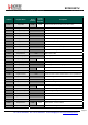
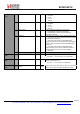
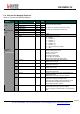
6.4. Receiver Registers
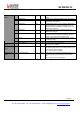
Table 26 Receiver Registers
Name
(Address)
Bits Variable Name Mode
Default
Value
Description
Reserved14
(0x14)
7-0 - r 0x40 unused
Reserved15
(0x15)
7-0 - r 0xB0 unused
Reserved16
(0x16)
7-0 - r 0x7B unused
Reserved17
(0x17)
7-0 - r 0x9B unused
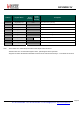
7 LnaZin rw 1
*
LNA’s input impedance
0 → 50 ohms
1 → 200 ohms
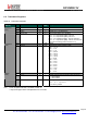
6 - r 0 unused
5-3 LnaCurrentGain r 001 Current LNA gain, set either manually, or by the AGC
RegLna
(0x18)
2-0 LnaGainSelect rw 000 LNA gain setting:
000 → gain set by the internal AGC loop
001 → G1 = highest gain
010 → G2 = highest gain – 6 dB
011 → G3 = highest gain – 12 dB
100 → G4 = highest gain – 24 dB
101 → G5 = highest gain – 36 dB
110 → G6 = highest gain – 48 dB
111 → reserved
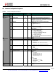
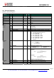
7-5 DccFreq rw 010
*
Cut-off frequency of the DC offset canceller (DCC):
-----
-----------------
~4% of the RxBw by default
4-3 RxBwMant rw 10
*
Channel filter bandwidth control:
00 → RxBwMant = 16 10 → RxBwMant = 24
01 → RxBwMant = 20 11 → reserved
RegRxBw
(0x19)
2-0 RxBwExp rw 101
*
Channel filter bandwidth control:
FSK Mode:
RxBw =
------------------------
F
----
X
----
O
----
S
----
C
-------------------------
RxBwMant
∗
2
RxBwExp + 2
OOK Mode:
RxBw =
------------------------
F
----
X
----
O
----
S
----
C
-------------------------
RxBwMant
∗
2
RxBwExp + 3
See Table 14 for tabulated values
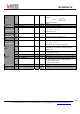
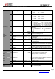
7-5 DccFreqAfc rw 100 DccFreq parameter used during the AFC
4-3 RxBwMantAfc rw 01 RxBwMant parameter used during the AFC
RegAfcBw
(0x1A)
2-0 RxBwExpAfc rw 011 * RxBwExp parameter used during the AFC